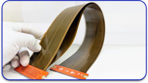
The coming of flexible printed circuit boards (Flex PCBs) had a significant impact on the electronic world because of their lightweight, space efficiency, and versatile traits. Maximum flexibility in the design of these Flex PCBs can only be achieved if best practices which enhance reliability are observed. Whether you are working with flex circuit board manufacturers for the first time or doing your very first project, these five design tips will assist you optimize your flex PCB.
1. Evaluate the Flexibility Level of Your Flex PCB
The major advantage of the flex PCB is its ability to bend into the desired shapes. If it is not properly designed, mechanical failures or signal integrity challenges may arise. Knowing the flexing radius of a PCB is key to achieving reliability and longevity.
Key Features:
- Bend Radius: A maximum bend radius should be set in order to avoid excessive tension on the conductive traces. A general principle is a 10:1 ratio of the flexing thickness to the bend radius.
- Dynamic vs. Static Flexing: Confirm if your PCB will undergo continuous bending (dynamic) or stay in one position (static). Design considerations are stiffer for dynamic flex circuits.
- Avoiding Stress Points: Sharp corners should be avoided. Curved traces are more suitable, and keeping traces perpendicular to the bend area is recommended.
2. Know Your Flex PCB Materials
Choosing the appropriate materials is an essential step toward making a good flex PCB. Knowing the different mechanical properties of the materials will help in the optimization.
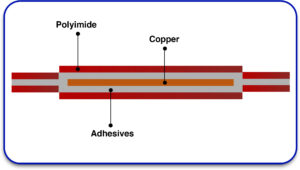
Basic Flex Materials
- Polyimide (PI) – It is the most popular substrate due to its exceptional thermal and electrical properties.
- Adhesives – Usually used for lamination but could affect flexibility.
- Two Types of Flex Materials
- Rolled Annealed Copper – Delivers higher flexibility and better fatigue performance than electro-deposited copper.
- Electro-Deposited Copper – Has a high conductivity, however, it is susceptible to cracking during dynamic flex applications.
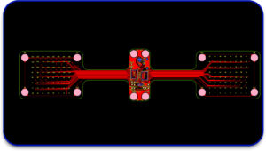
3. Keep an Eye on Flex Board Layout and Routing
Routing and design are fundamental factors for the performance of a flex PCB. Supervised and controlled trace width, spacing, and placement of the via are essential to prevent mismatches of impedance and stress on the mechanism.
Via Design Considerations in Flex Boards
- Teardrop Pads help to release stress, so it is common practice to apply them to the flex vias.
- Lower Vias Count – Redundant vias could lead to loss of flexibility and increased rate of failure.
- Reinforced Vias: Use reinforced vias in dynamic flex scenarios where durability is needed.
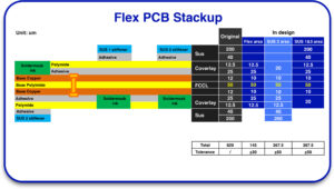
4. Determine Flex PCB Stack-Up and Whatever Works Best
Selecting a flex PCB stack-up is critical for mechanical strength and electrical function. The stack-up ought to consider support for shielding, impedance control, and bending.
Flex PCB Stack-Up Design Case Study
For instance, there is a two-layer flex PCB used in a wearable device which may have the following configuration.
Layer 1: Signal layer: Rolled Annealed Copper
Dielectric: Polyimide core
Layer 2: Ground plane: Rolled Annealed Copper
Controlled Impedance and EMI Shielding
To achieve signal fidelity while reducing electromagnetic interference, the following should be ensured:
Use controlled impedance routing for polarity sensitive low speed signals.
Where applicable, noise reduction shielding layers need to be incorporated.
Consistent trace width with controlled spacing are employed to mitigate impedance change.
5. Adhere to Flex PCB Specific IPC Design, Manufacturing, and Testing Standards for Compliance
Creating a flex PCB always comes with the assurance of dependability and compliance with industry quality standards. The standards set by IPC are very specific and aid in the quality control of design, assembly, and testing processes.
Essential IPC Requirements When Designing a Flex PCB
- IPC-2221: The generic standard for printed boards design
- IPC-2223: The sectional design standard for flexible printed boards and rigid flex printed boards,
- IPC-FC-234: Covers flexible material characteristics and selection.
- IPC-6013: The performance and qualification specification for flexible printed circuit boards.
- IPC-600: Establishes visual acceptability requirements for printed boards.
- IPC-A-610 and IPC/EIA J-STD001: Address the acceptability and soldering of electronic assemblies

Proper preparation and practices must be followed to design a reliable and effective Flex PCB. Understanding bendability, material selection, layout and routing, stack-up, and adherence to standards is essential to achieving success in a Flex PCB project. Qualified Flex Circuit Board manufacturers can improve the integrity and effectiveness of the design.
By adopting these five tips on flex PCB design, engineers and designers can achieve more reliable, high-quality, and efficient flexible circuit board solutions for a wider range of applications.


