High-speed data transfer has become a necessity as the world around us is getting more and more advanced. To keep up with this, different devices are making use of differential signaling on both flex and rigid boards. However, implementing differential signals in flex-printed circuit boards turns out to be pretty difficult for flexible printed circuit manufacturers.
So, let’s elaborate on what flex circuits are and their importance when it comes to differential signaling.
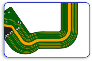
Flex circuits, also known as flexible printed circuits (FPCs), are electronic circuits fabricated on flexible substrates, typically made of polyimide or similar materials. They are designed to bend, twist, and conform to specific shapes, making them ideal for applications where rigid circuit boards are impractical. Flex circuits are widely used in industries such as consumer electronics, medical devices, aerospace, and automotive systems due to their lightweight, compact design, and ability to reduce wiring complexity.
They can support high-density interconnects and are often used in dynamic or space-constrained environments where traditional rigid boards would fail. For businesses seeking reliable solutions, partnering with experienced flexible printed circuit manufacturers or flex circuit board manufacturers ensures high-quality production and adherence to industry standards.
When it comes to differential signaling, flex circuits play a critical role in maintaining signal integrity, especially in high-speed data transmission applications. Differential signaling relies on two complementary signals transmitted over paired traces to reduce electromagnetic interference (EMI) and improve noise immunity.
Flex circuits are well-suited for this purpose because they allow precise control over trace geometry, spacing, and impedance, which are essential for maintaining the balance required in differential pairs. Additionally, the flexibility of the substrate helps minimize mechanical stress on the traces, ensuring consistent performance even in environments with movement or vibration.
This makes flex circuits an excellent choice for applications like high-speed data buses, USB, HDMI, and other differential signaling protocols. Collaborating with reputable flexible printed circuit manufacturers or flex circuit board manufacturers ensures that these critical design parameters are met, delivering optimal performance for advanced electronic systems.
What is Differential Signaling?
Differential signaling is a method used in electronics to transmit data reliably, especially in environments where interference or noise can disrupt signals. It works by using two transmission lines (wires or traces) to carry two complementary signals simultaneously. These signals are mirror opposites of each other—when one line carries a positive voltage, the other carries an equal but negative voltage. The key advantage of this approach is that the receiving device reads the difference between the two signals, rather than relying on the absolute voltage of a single line. This makes the signal more robust against external interference and noise.
To better understand how this works, let’s break it down with an example. Imagine line A sends a voltage of +1.75V, while line B sends -1.25V at the same time. The receiving device calculates the difference between these two voltages, which in this case is 1.75V – (-1.25V) = 3.0V. This difference is the actual signal that is processed. Even if external noise affects both lines equally (e.g., adding 0.2V to both), the difference remains the same: (1.75V + 0.2V) – (-1.25V + 0.2V) = 3.0V. This consistency ensures that the signal stays clear and accurate, regardless of interference.
For applications requiring precise signal routing, flexible printed circuit manufacturers play a vital role in designing circuits that support differential signaling. By focusing on the voltage difference rather than the individual signals, differential signaling provides a reliable and consistent way to transmit data over long distances or in noisy environments.
Why Differentiate Signals In Flex Circuit?
Differential signaling is used in flex circuits for the following reasons:
- Weak Ground Connections: The ground between the elements is not always stable. Differential signals maintain signals.
- High Data Rate Needs: With HDMI, USB, or PCI Express fully integrated, differential pairs allow for easy sending and receiving of an immense amount of data.
- Enhanced Noise Cancellation: Since signals are transmitted together, noise from the exterior will have the same effect on both lines and will cancel each other out.
Designing Flex Circuits for Differential Signaling
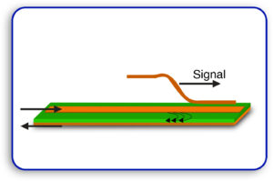
For differential signaling, surface microstrip transmission lines are usually utilized by engineers when making flexible printed circuits. Here are its parts:
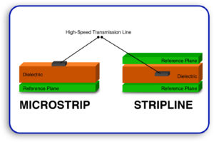
1. Surface Microstrip versus Stripline
Microstrip: Where one side of a double-sided material is etched so that its traces are exposed to air and referenced to a ground plane.
Stripline: Increases thickness but shields the trace by sandwiching it between two copper layers.
Flex circuits prefer microstrip design because it makes PCBs thinner and, hence, more flexible, which is necessary in the construction of compact and portable electronics.
2. Controlled Impedance
Controlled impedance is of utmost importance for signals traveling at high speeds. The flexible printed circuit manufacturers place differential pairs at optimal spacing and ensure that the spacing, thickness, and trace width are best suited for differential pairs.
3.Shielding Techniques
Signals can suffer from electromagnetic interference (EMI), so depending on the place of use, shielding measures may be needed. Using a thinner layer of copper along with a thoughtfully designed core increases flexibility and mechanical strength.
The Role of Cross-Hatched Ground Planes
Flexible PCBs typically use cross-hatched or mesh ground planes instead of copper solid planes. The shape of these planes is lattice-style, and they provide several benefits, including:
- Impedance Control: The lattice mesh reduces capacitance while raising impedance so that signals can be transmitted without loss.
- Structural Support: Rather than making the entire board rigid, it strengthens flex regions.
- Flexibility: The board can bend more easily than solid copper planes due to the mesh structure.
Although cross-hatching has advantages, it also brings problems, such as signal distortion, caused by differences in dielectric constant compared to the unmated plane. These problems can be dealt with proper design considerations.
Tips for Reducing Signal Distortion
Several basic principles must be followed to reduce signal quality problems that may stem from a dielectric variety or interconnect length in flex circuits.
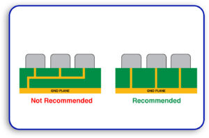
- Pattern Optimization: Always use the diamond cross-hatch optimum pattern rather than the cross square.
- Spacing: Avoid distortion by manufacturing the cross-hatch pattern spacing limits to 1.27mm (50 mils).
- Alignment: Cross-hatch intersections should be straddled by differential pairs in order to reduce crosstalk.
Benefits of Differential Signaling
Here’s why many flex circuit board manufacturers favor differential signaling:
- Noise Resistance: When signals are transmitted, this mode escapes the copper mesh lattice, canceling stereo noise from common-level signals.
- Faster Signal Speeds: Data at gigabit speeds is easily transmitted by differential pairs.
- Power Efficient: This type of structure helps in power saving compared to single-ended signals.
- Reducing EMI: EMI was managed by routing signals efficiently through noisy environments.
Challenges and Solutions
Differential signaling is highly favorable. However, certain challenges should be taken into account.
- Routing Balance: The routing has to be done carefully to ensure balanced signals.
- Control Lengths: Differential pair trace lengths have to be controlled.
- Achieve Matching: Controlled impedance is vital for proper function.
Geometric optimization allows modifying the shape of the trace and arranging the layout to avoid some of the challenges mentioned above.
Best Routing Tips for Flex PCBs
These simple best practices should be worked into routing differential pairs flex circuit boards:
- Equal Trace Length: Same length for differential pairs.
- Control Impedance: Width, spacing, and thickness should be done appropriately.
- Control Spacing: Do not allow enough space for traces to crosstalk.
- Control Bends: Closer controls on bends in the routing path should be enforced.
- Routing Copper Pour: For more efficient topology routing, stitching vias should be utilized.
Advanced flex PCB design plays a pivotal role in enabling high-performance differential signaling. By leveraging the flexibility, precision, and durability of flex circuits, engineers can achieve superior signal integrity, reduced noise, and reliable data transmission—even in the most demanding environments. Whether it’s for high-speed data buses, medical devices, or aerospace systems, the ability to design flex PCBs that handle differential signaling effectively is a game-changer.
For businesses and engineers seeking cutting-edge solutions, partnering with experienced flexible printed circuit manufacturers like Blind Buried Circuits is essential. As a trusted name in the industry, Blind Buried Circuits brings unparalleled expertise in designing and manufacturing high-quality flex PCBs tailored to meet the stringent requirements of differential signaling. Their advanced capabilities ensure optimal performance, whether you’re working on complex multi-layer designs or space-constrained applications.
Ready to elevate your flex PCB designs? Reach out to Blind Buried Circuits today and discover how their innovative solutions can bring your next project to life. Let’s build the future of electronics together


