Have you ever experienced any costly blunders or delays in your PCB fabrication? Incomplete documentation is one of the major contributors to such problems. Whether you are working on a straightforward circuit design or a complex multilayer board, proper design documentation is crucial for flawless manufacturing.Your PCB board manufacturer is likely to fail to deliver the product you want if he does not have adequate information regarding your design. In such a case, you are bound to experience delays, errors, or worse – failure of the product altogether. To prevent these problems, best practice standards for PCB documentation must be observed.
This blog will discuss the major components of PCB documentation, the most important standards, and PCB design best practices for production.
Importance of PCB Design Documentation
A design for your PCB serves as the detailed outline for construction and its assembly. It contains the essential information needed by fabricators, assemblers, and testers to correctly construct the PCB. If you do not have clear documentation, you face the risk of:
- Errors in manufacturing caused by misinterpretations.
- An increase in costs resulting from rework and scrapping.
- Production holdups resulting from insufficient information.
- Failures due to inaccurate component placement.
Ensuring structured and comprehensive PCB documentation helps in creating a seamless workflow from design all the way to production.
Fundamental Files Needed for PCB Board Manufacturer and Assembler
While sending your design to a PCB Manufacturer, make sure the following document files are prepared:
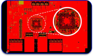
1. Gerber Files
These files hold all of the engineering graphics necessary for building your PCB, such as:
- Copper layers (traces and pads).
- Layers of solder mask and silkscreen.
- Positions and diameters of drill holes.
- Mechanical features and contours of the board.
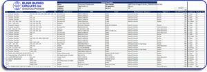
2. Bill of Materials (BOM)
All components on the PCB are captured in the BOM. Well-defined BOM features:
- Component designators and titles.
- Market part designation in case of purchase (MPN).
- Required quantities for production.
- Sources for Procurement for grants easily.
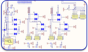
3. Schematic Diagram
A schematic acts as a guide for all of the electrical interconnections of a system. It assists to:
- Resolve mistakes in circuits prior to physically fabricating the system.
- Ensure precision of placement for components.
- Aid assembly groups to grasp the circuit’s behavior during assembly.
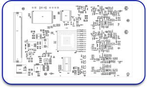
4. Assembly Drawings
These diagrams specify how the components are to be located and oriented concerning the board. These include:
- Views of the upper and lower layer.
- Markings of the polarity of the capacitors, the diodes, and the ICs.
- Probe points for fault finding.
5. Drill Files (NC Drill Files)
These documents define the locations for drilling holes, which include:
- Openings for through-hole parts.
- Vias for inter-layer electrical connections.
- Holes for attachments of boxes.
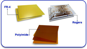
6. Fabrication Drawing
This document contains general information about the trade, including:
-
Material Specifics: FR-4, Rogers, Polyimide.
7. Specifications for auditing and testing
For quality control purposes, kindly include:
- Electrical check test points.
- Automated Optical Inspection (AOI) data.
- Guidelines for Flying Probes and In-Circuit Test (ICT).

Key PCB Documentation Standards
To ensure your design meets industry requirements, follow these essential PCB documentation standards:
1. IPC-2221. General Standard for PCB Design
Describes requirements for layout, materials, and performance of PCB.
2. IPC-2581. Standard for Data Exchange
Contains all details on fabrication and assembly in a single file.
3. IPC-6012. Qualification and Performance
Rigid PCB quality standards.
4. J-STD-001. Soldering Standard
Constructional Assembly Soldering of Printed Boards.
5. ISO 9001
Quality control standards for PCB manufacturers.
With these standards, the reliability of PCB manufacturing will be increased while production risks will be decreased.
Important Guidelines for PCB Design Documentation
1. Simplify and Organize Information
- Apply consistent naming rules like (Project_TopLayer.gbr).
- Names of items within BOMs and drawings should be self-descriptive.
- Do not use vague acronyms.
2. Implement a Centralized Database
- All documents should be placed in one database for easier access.
- There should be a record of changes for version control.
- All users of the database should have the most recent version.
3. Check the design files prior to submission
- Design Rule Check (DRC) for layout check:
- Conduct ERC analysis to confirm the circuit’s compliance.
- Use tools to find problems with signal integrity, using simulations.
4. Step With Your PCB Firm On Manufacturing Processes
Resolve issues regarding the fabrication process’ limitations for the design is done.
- Get feedback on DFM documentation.
- Check that all the parts are in stock.
5. Add Notes for Special Instructions On Manufacturing
- Indicate details on solder mask colors, silkscreen and other finishes.
- Call attention to the rigorously defined tolerances.
Set rules for panelization, in case some parts are populated on a single board.
6. Maintain Different Physical Copies Of All Documentation
- Make duplicates of documents to different secured areas.
- Document all changes made, so that the history is retrievable.
The Most Frequent Errors In Documenting PCBs
1. Missing Details In Bills of Materials
Failing to include sufficient information can delay getting parts and result in wrong ones being sourced.
2. Omitted Drill Files
With no drill file identifiers, holes will not be where they should be, or do not exist at all.
3. Assembly Instructions That Lack Clarity
Left needed instruction that does not give a clear guide, parts will be positioned wrongly.
4. Failure To Observe Accepted Practices
Neglect of IPC or ISO rules often leads to quality problems in production.
5. Absence Of Adequate Control in Files Changes
Applying the wrong file version will trigger problems and errors instead of solving them.
How Blind Buried Circuits Aid in Gaining Circuit Assistance
To assist you with your needs, Blind Buried Circuits is deeply aware of how precise documentation is for successful PCB manufacturing. We ensure that the documentation in design files is complete and that everything is in the right form to facilitate production.
- Fast PCB manufacturing with accompanying quality assurance.
- Tailored Custom Services of PCB manufacturing.
- Reliable production of bare printed circuit boards in compliance with IPC Norms and other stipulated industry requirements.
- Comprehensive Services for PCB fabrication and assembly.
Flawless documentation plus zero production delays amounts to building your next PCB seamlessly. Get in touch with us now!
Proper documentation in PCBs saves time, decreases the number of mistakes, and guarantees a higher quality of manufacturing. The standards also contain recommendations that will facilitate fast production and will minimize naturally expensive mistakes. Are you looking to make substantial changes to your PCB design documentation? Collaborate with any skilled PCB board manufacturer like Blind Buried Circuits and guarantee a hassle-free process.


