If you’re working with high-speed PCBs, especially HDI boards, you’ve probably heard the term “TDR impedance.” But what is it really? And why does it matter in Custom PCB manufacturing?
In simple words, TDR impedance tells you how smooth or bumpy a signal’s ride is across a circuit board. If the ride isn’t smooth, your signals may bounce back, get distorted, or slow down. That can mess up the whole system.This blog will explain what TDR impedance is, how it’s measured, and why it plays a key role in high-speed electronics, especially in today’s fast-growing tech fields like 5G, data centers, and advanced medical equipment.
What Is TDR Impedance?
TDR stands for Time Domain Reflectometry. It’s a method that helps you check if a circuit path, like a trace or a cable, has the right impedance. Impedance is like road width for electrical signals. If the road suddenly gets narrow or wide, the signal might bounce back, just like a car might swerve or hit a bump. TDR impedance shows if the “road” on your PCB is consistent and smooth. If not, the system may suffer from signal loss or interference.
Why Is It Important in PCB Design?
In bare boards, impedance might not be a big issue. But in fast, complex boards like HDI boards, signal speed matters a lot. Even minor bumps can cause big problems.
Here’s why TDR impedance is essential:
- Avoids signal reflections: A sudden change in impedance reflects the signal, like an echo.
- Keeps signal strength strong: Reflections reduce power and data accuracy.
- Improves timing: Smooth paths help signals reach the destination at the right time.
- Helps in debugging: If a signal isn’t working right, TDR can find where the issue is.
When done right, Custom PCB manufacturing includes TDR checks to make sure every trace meets the target impedance.
How Time Domain Reflectometry Works
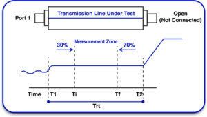
Time Domain Reflectometry sends a quick electrical pulse down a trace or cable. If the path is clean and consistent, the signal keeps going. If there’s a break, change in width, or poor solder joint, part of the signal reflects.
The system measures two things:
- Time: How long it takes for the reflection to return
- Voltage: How strong the reflection is
This tells you both the location and size of the problem.
Think of it like shouting into a tunnel. If there’s a bump, you’ll hear the echo and know something’s there. That’s how tdr cable test works in electronics.
What Tools Are Used in TDR Testing?
To check TDR impedance, engineers use tools like:
- TDR test sets: These plug into PCB traces and send pulses
- TDR scopes: These show a graph of the signal and reflections
- Automatic TDR analyzers: Used in mass PCB testing in factories
These tools help PCB manufacturers spot and fix problems before shipping the boards.
When Is TDR Testing Used?
TDR cable test and trace testing is used:
- During PCB prototyping
- In mass production testing
- For failure analysis in the field
- When impedance control is required (common in 5G, routers, and antennas)
It’s especially common in Custom PCB manufacturing for industries like aerospace, telecom, and medical.
Common TDR Testing Issues
Even if you use the best tools, some problems may still show up:
- Noise: Random voltage spikes can confuse the readings
- Parasitics: Extra inductance or capacitance from test probes
- Poor calibration: Leads to wrong measurements
- Bad board design: Uneven trace widths, poor grounding, or sharp corners can cause reflections
That’s why working with skilled engineers and reliable PCB manufacturing partners is essential.
What’s the Target Impedance?
In most digital systems, the target impedance is:
- 50 ohms for single-ended traces
- 100 ohms for differential pairs (used in USB, Ethernet, HDMI, etc.)
HDI boards, with their tight layouts and fine traces, make it hard to hold this value. So, design rules must be clear from the start.
Your Custom PCB manufacturing partner should support impedance modeling and test every batch with TDR tools.
Frequency Domain Reflectometry (FDR) – A Quick Note
Frequency Domain Reflectometry is another way to measure impedance, but it uses sine waves at different frequencies instead of pulses. FDR is used more for long cables or antennas.
While Time Domain Reflectometry is better for short traces (like on PCBs), FDR gives detailed info on frequency performance. It’s less common in PCB shops but helpful in labs or RF systems.
TDR in High-Density Interconnect (HDI) Boards
HDI boards have lots of small parts and fine traces. They use micro vias, buried vias, and multiple signal layers.
In these boards:
- Traces are shorter but faster
- Vias add small impedance bumps.
- TDR checks must be extra precise
Even a 0.5-ohm bump in a 2-inch trace can mess up signal timing in HDI boards.
That’s why Custom PCB manufacturing for HDI always includes impedance control. Your PCB vendor should offer TDR testing during production to ensure your designs meet specs.
What Happens If You Skip TDR?
Skipping TDR impedance checks can cause:
- Signal reflection: Corrupted data
- Crosstalk: One signal interfering with another
- Timing errors: Devices don’t sync
- Field failures: Costly product recalls
In short, skipping TDR is risky, especially in sensitive industries like medical, defense, and 5G.
Choosing the Right PCB Manufacturer
If impedance matters in your board, choose a partner that offers:
- Built-in TDR testing
- Design for impedance services
- Clear traceability and test reports
- Support for complex HDI boards
- Experience with time-domain reflectometry and frequency-domain reflectometry
This ensures fewer delays, fewer bugs, and better performance.
Final Thoughts
In today’s high-speed world, electrical signals can’t afford delays or reflections. That’s why TDR impedance testing is key in Custom PCB manufacturing, especially when working with HDI boards or high-frequency circuits.
With tools like the TDR cable test and frequency domain reflectometry, you can find hidden issues before they become big problems. Whether you’re building a next-gen router, a medical scanner, or a drone, make sure your PCB design includes impedance control and your manufacturing partner knows how to test it.
That small step could save you thousands later.


