Confused about PCB design rules? If you’re building a printed circuit board (PCB), following the right standards can save you from major rework. That’s where IPC-2221 comes in, the foundation of PCB design guidelines used worldwide. IPC-2221 helps you design better, more reliable, and industry-compliant PCBs, whether you’re working with simple two-layer boards or advanced rigid-flex PCB manufacturer projects.
What Is IPC-2221?
IPC-2221 is a universal standard developed by IPC (Institute for Printed Circuits) that provides essential PCB board design rules. It applies to nearly all types of boards, including:
- Rigid PCBs
- Flexible circuits
- Rigid-flex PCBs
- High-density interconnect (HDI) boards
The standard outlines how wide your traces should be, how much spacing you need between them, and how to handle thermal management, mechanical stability, and even material choice. It ensures that your main board design meets safety and performance expectations.
Why Should You Care About Printed Circuit Board Standards?
You might be wondering: “Do I really need to follow this?” The answer is yes, especially if:
- You’re designing for mass production
- You want to pass regulatory inspections
- You’re working with a PCB manufacturing assembly partner
- You need to ensure high reliability in complex systems
Ignoring printed circuit board standards like IPC-2221 can result in:
- Electrical shorts
- Signal integrity issues
- Inconsistent manufacturing results
- Product recalls or field failures
In short, following IPC-2221 helps your board work right the first time.
Key Elements of IPC-2221
Let’s look at the most critical areas covered by this standard:
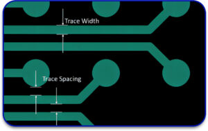
1. Conductor Width and Spacing
IPC-2221 gives exact numbers for trace width and spacing based on current-carrying capacity and voltage requirements. These values help prevent overheating and electrical shorts.
Example: If you’re doing flexible PCB fabrication, you might need narrower traces but still meet the current load , IPC-2221 tells you how to balance those trade-offs.
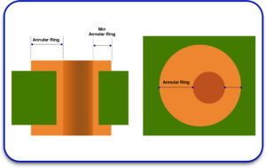
2. Pad Design and Via Sizes
Proper pad size ensures strong solder joints. The standard defines:
- Minimum annular ring size
- Aspect ratio of vias (hole depth vs. diameter)
- Tolerances for drilling
These details are critical for high-density mainboard design and automated assembly.
3. Thermal Management
Whether you’re building power supply circuits or RF systems, thermal relief matters. IPC-2221 helps you:
- Calculate the copper area needed for heat dissipation
- Design thermal pads
- Select proper materials (e.g., copper weights)
Especially in PCB manufacturing assembly, these guidelines ensure your board won’t overheat during operation.

4. Mechanical Stability
Rigid and flexible PCBs are fabricated according to the IPC-2221 standard. This document details mechanical limits such as board thickness and hole centers, as well as flex areas. This is essential for:
- Preventing warpage
- Providing support for connectors or major components
- Structural integrity over time in extreme conditions
Working with a rigid flex PCB manufacturer? Design governed by IPC-2221 saves from layout changes that are expensive and time-consuming.
5. Clearance Rules for Voltage Levels
The standard defines the minimum clearance zone between the conductors which ensures spacings and distances junctures between the active conductors (creepage) for safety. This is most important for board design in industrial, automotive, or medical environments.
Real Life Example: Flexible PCB Fabrication
If you are working on a health monitoring device worn on the body, the board would need to flex, require low power, and be safe for daily handling. While observing IPC-2221:
- You create non-cracking traces during flexing
- Your flexible PCB fabrication company delivers reliable output
- You prevent failures from insufficient clearance or faulty soldering
How IPC-2221 Affects PCB Manufacturing and Assembly
As soon as you send the design over to a PCB manufacturing assembly company, IPC-2221 becomes our guide. Now they can:
- Fabricate alignment accurate boards
- Drill and place vias according to the design
- Securely solder components using appropriate pad sizes
In summary, manufacturing yield increased while time-to-market decreased.
The Importance of IPC-2221 for Rigid Flex Boards
The aerospace, military, medical, and advanced consumer electronics industries utilize rigid-flex PCBs due to their need for precise mechanical and electrical performance. The blend of rigid and flexible layers enables compact designs and dynamic movement, but presents unique design challenges at the same time. IPC-2221 is the generic standard for PCB design which, in this case, helps overcome these design problems. It offers exhaustive design rules which the engineers need to focus on in order to assure performance, reliability, and ease of manufacturing.
Proper Bend Radius and Trace Positioning
Preventing mechanical failure in the bendable, flexible portions is the most critical aspect of achieving desirable rigid-flex PCB design. Flexed or bent boards may experience trace cracking along with delamination of laminates if bend design guidelines are not suitably followed. As with all trace design recommendations including those IPC-2221 specifications for minimum bend radius, they are provided based on material type, copper thickness, and number of layers. It also sets boundaries on trace design aimed at alleviating stress concentration and fracture during repetitive flex cycles. By absent of these restrictions, PCB designers can improve the mechanical lifespan of the board significantly.
Choosing A Trustworthy Layer Stack-Up
Rigid-flex designs require critical thought on how different materials and layers interact, particularly in the boundaries between rigid and flexible areas. IPC-2221 aids in the definition of balanced stack-ups engineers termed as “stress optimized” that can survive thermal expansion, shudder, and cyclic movement. It addresses dielectric selection, adhesive characteristics, copper allocation, and copper distribution on the board to guarantee structural and electric reliability under extreme conditions.
Regulated Impedance Control for Flexible Regions
For high speed or RF applications, maintaining the same signal quality reassured is critical on flexible areas. The flexible layers if not designed carefully would pose a risk of non-uniform impedance that could lead to signal integrity issues. Trace width, space, and materials selection IPC-2221 helps in yielding and maintaining impedance which improves reflection, attenuation, and crosstalk which are vital in aerospace datalink systems and medical imaging equipment.
Standards compliance with improving ease of manufacturability
Leading companies that manufacture top rigid-flex PCBs use IPC-2221 not just to conform to industry expectations, but optimally streamline production. Aligning design, all empirical methods and simulation runs give proof that the document aligns to IPC-2221 requirements guarantees traceable standards in baseline processes. This eliminates the probable cause of defects during manufacturing, enhances the first-pass yield, and ease of interaction between the design departments and the fabricators.
What IPC-2221 Helps You Control
| Design Aspect | How IPC-2221 Helps |
| Trace Width & Spacing | Ensures safe current flow and avoids shorts |
| Pad & Via Dimensions | Improves soldering and structural strength |
| Thermal Relief | Prevents overheating and component failure |
| Mechanical Design | Increases durability and product life |
| Clearance & Safety | Meets voltage safety standards |
Final Thoughts
What is the importance of IPC-2221 in PCB design? It serves the purpose of offering a safe, reliable, and efficient layout for safe, reliable, and efficient board layouts. In the case that you need to design a rigid, flex, or rigid-flex PCB, this standard assists in every decision, from the width of a trace to the spacing of a pad. In addition, it facilitates PCB manufacturing assembly, minimizes expensive revisions, and improves overall product performance (value) from design to production. If there are any doubts regarding the compliance of your board with IPC-2221, it’s time to go through the board with a checklist. Check with your PCB fabrication partner to check compliance or use design checklists to begin verification processes.
If you need supporting guidance IPC compliant designs or fabrication, don’t wait and contact well-known experts in flexible PCB fabrication and mainboard design for unrivaled reliability.


