Humanoid robots are programmed to complete tasks that imitate human actions. The usage of these robots has bloomed in different sectors, from manufacturing to healthcare. For humanoid robots to function as intended, however, a fundamental aspect is needed, which is reliable printed circuit boards (PCBs). These PCBs permit the integration of the robot’s parts, ranging from sensors to motors. Given the advanced nature of these robots, it’s evident that the reliability of the PCB is of utmost importance. This is where advanced methods of testing PCBs come in.
In this blog, we will highlight some of the best testing techniques used in testing the PCBs of humanoid robotics. We will also discuss why testing is essential and how it assures the user that the tested PCBs are indeed reliable.
The Importance of PCB Testing for Humanoid Robotics
Before highlighting the various methods of testing the PCB, it is essential to touch on why testing, in general, is important. Every robot, including the humanoid version, relies heavily on its PCBs.
- The performance of the robot’s motors, as well as its sensors, are all dependent on the PCBs.
- A problem with a PCB can disrupt the entire system and the robot fails to operate correctly.
When it comes to humanoid robots, there is absolutely no room for error. They might need to execute intricate operations in unstructured real-life settings. Malfunctions, such as damaging the robot, can arise due to issues with the PCB. Thus, robust testing must be included during the PCB board assembly manufacturing process to make sure that the PCB functions optimally under every measure.
Testing Methods for PCBs in Humanoid Robotics
Let’s discuss robotic PCB design and the most prevalent yet efficient testing methodologies for PCBs intended for humanoid robots. These methodologies make sure that the requirements for humanoid robots are precisely met.
1. In-Circuit Testing (ICT)
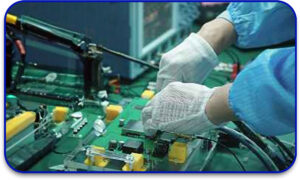
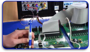
Individual components of a PCB are tested within the circuit during in-circuit testing (ICT). It is one of the most common testing methodologies of PCBs. Verification of constituent parts functioning appropriately is ensured by this method. Also checked are the connections and soldering of the board.
Evaluation of robotics PCB design involves ICT. It assists in revealing minute errors that could later escalate into problematic situations.
If a solder joint is incorrect or if a component is placed incorrectly, ICT will catch it immediately. This guarantees that the PCB will be dependable when installed onto the robot after assembly.
2. Functional Testing
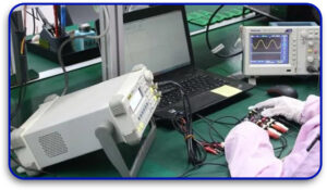
Functional testing is slightly different from in-circuit verification testing. In-circuit testing verifies each component’s functionalities separately. In contrast, functional testing assesses how the whole system operates, which, in this case, is measuring the performance of the PCB while it is placed in the robot.
During the testing of a humanoid robot, functional testing could check how well the motor control PCB functions during movement and also test how the sensor PCB responds to external signals. This approach is essential for reliable humanoid robotics systems because it performs the actual intended robot usage. Any concerns raised during functional testing can prompt design changes to the PCB before it goes into production.
3. X-ray Inspection
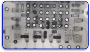
X-ray inspection is a non-destructive type of inspection that enables engineers to view the internals of the PCB for defects. This is very important for multi-layered PCB standards in humanoid robots. The X-ray machine has the opportunity to peep into the PCB to check for connection integrity and any hidden inter-layer defects.
For defects such as cold solder joints, voids, and other concealed faults, this technique is very useful in the assembly of PCBs.
Due to quite a few custom PCBs having densely packed components, x-ray inspection can pick up defects that would otherwise be difficult to appreciate. This helps ensure that the quality goals set for PCB production USA are met.
4. Flying Probe Testing
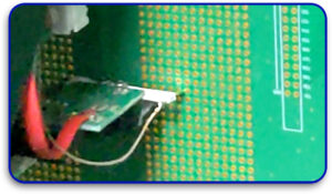
This is the type of testing where moving test probes are used to check a PCB for faults. In-circuit testing requires fixed test points, while flying probes have access to multiple locations of the board, allowing for easy access without a dedicated test fixture. This is advantageous for custom PCB designs or low-volume production runs.
In robotic PCB design, which is often elaborate and sophisticated, flying probe testing is automatic. It is used to detect electrical shorts, open circuits, and other common issues that plague PCB board assembly manufacturing. This technique is best to adopt during the early stages of production, especially for high-density PCB connectors and has become commonplace.
5. Boundary Scan Testing
This is a more advanced testing method. It is used for high-density PCBs with very few testing points or ports and sockets for testing. This technique uses an exceptional test architecture that is built into the design of the PCB. Engineers are able to check the board’s connections and components without having pre-defined test points on the board.
HDI PCBs, including those designed for humanoid robotics, benefit significantly from boundary scan testing.
The fault detection test architecture enables the engineers to identify issues such as open or short circuits without exposing every component. This diagnostic step makes certain the PCB is electrically good and physically connected right before integration within the robotic systems.
6. Thermal Cycling Testing
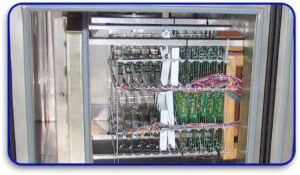
Robots are often exploited to work in areas with fluctuating temperature conditions. Thermal cycling testing is done to check if the PCB will fail when subjected to these temperature variations. The PCB undergoes repeated heated and cooled cycles to mimic what conditions are expected to be during its lifetime.
Thermal cycling becomes really important for humanoid robotics with high reliability requirements. It determines the weaknesses within a PCB that are likely to fail due to excess heat. Early discovery of these weaknesses allows engineers to improve the functionality as well as survivability of PCBs in robots, allowing smooth functionality in extreme conditions.
Learn About: PCB Thermal Profiling in PCB Assembly
7. Burn-In Testing
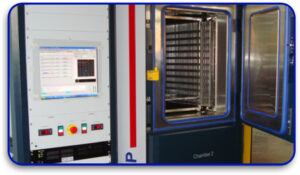
Burn-in testing focuses on using extreme temperatures to test the durability of the PCB. Simulated long-term conditions where high voltage and high current are applied for long periods identify reliability issues. This has proven useful, revealing issues previously unnoticeable under standard conditions.
Burn-in testing in robotics PCB design becomes crucial since it guarantees that the piece of hardware continues functioning as time progresses.
The reasoning behind performing burn-in testing remains the same. It ensures that the PCB is not likely to fail during mid-operation so that, in the long run, the humanoid robot is able to function at optimum levels. It is especially valuable when looking into high-replication robotics PCB assembly and where dependability becomes crucial.
Why These Testing Methods Matter for Robotics?
These modern methods of testing the PCBs within humanoid robots provide reasonable assurance that they have been designed adequately for the intended purpose. When put through rigorous testing, defects are identified early on, increasing the reliability of the PCB, which is critical because failure can pose serious risks, such as catastrophic robot malfunctions or complete system failure.
For PCB manufacturers or those affiliated with a PCB manufacturing firm, employing these sophisticated techniques undoubtedly enables them to produce dependable, trustworthy PCBs. Rigorous testing guarantees the adequate performance of the PCBs, even under the extreme conditions posed by humanoid robotics.
Conclusion: Ensuring Quality in PCB Manufacturing for Humanoid Robots
PCBs of humanoid robots are required to be long-lasting and reliable, performing the required tasks optimally. Employing modern testing such as in-circuit testing, functional testing, and X-ray inspection, one can ensure that their PCBs operate up to the high demands of robotics.
All of the instructions above will get you to test the product, whether you are developing a specific humanoid robot or designing a custom PCB. These approaches will guarantee a reliable product in real-life settings. Keeping in mind the current robotics competition, these PCB testing strategies will put you ahead of everyone. Testing each of your PCBs manufactured will prevent costly mistakes while enhancing the robot’s performance over time. With proper evaluation methods, the outcome of your PCB manufacturing assembly processes will be of the best caliber, enabling your robots to function dependably and efficiently.


