The electronics industry is growing rapidly, and the need for smaller, stronger, and highly efficient circuit boards is at an all-time high. Rigid-flex PCBs have become an essential part of modern devices because they possess the durability of rigid boards while also offering the versatility that flexible circuits provide. As a leading rigid-flex PCB manufacturer, the importance of air gap construction in enhancing flexibility is clear.
Still, these PCBs pose challenges regarding mechanical flexibility and electrical reliability. One possibility that has altered the landscape is the air gap construction technique, which addresses the problems in high-layered rigid-flex PCBs.
Understanding the Challenges of Rigid-Flex PCBs
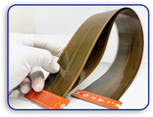
A rigid-flex PCB consists of a base with some rigid and flexible layers laminated onto it. This hybrid design makes it easier for designers to shrink the size and weight of electronic assemblies and is useful for industries like aerospace, medical, and consumer electronics.
However, there are many problems with high-layered rigid-flex PCBs, especially concerning mechanical and electrical reliability, which can affect flexible PCB fabrication:
Mechanical Reliability Problems
In many cases, a rigid-flex PCB using the basic structure must endure bending. Managing the mechanical flexure becomes a critical aspect as more layers are added. The flexible part of the thick board section increases along with stress on the copper traces.
For example, a flexible PCB with one or two layers requires a bend radius of ten times the flexing thickness, while a multilayered PCB with four or more layers needs a bend radius of thirty times its thickness. Exceeding these limits can cause mechanical failure or cracking of circuits, a key consideration for any rigid-flex PCB manufacturer.
Electrical Reliability Problems
The major challenge with these constructions is electrical reliability. These issues often arise from misalignment between rigid and flexible elements. In FR4 rigid-flex designs, FR4 materials are used for the rigid parts, and flexible parts are laminated with glue, epoxy, or acrylic separators.
The main issue in this construction is that the glue holding the flexible portions together has a higher thermal expansion coefficient (CTE) than FR4. CTE measures how materials expand and contract with temperature changes. When CTE is high, it can lead to stress on the vias and open circuits, making flexible PCB fabrication more complex.
What Is Air Gap Construction?
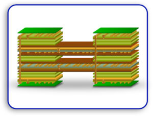
These problems can be mitigated by using air gap construction, a method pioneered by the IPC (Institute for Printed Circuits). Unlike traditional methods, it involves breaking the flexible layers into separate groups. Each group consists of no more than two to three layers, with two-layer groupings working best for flexibility.
Primary Aspects of Air Gap Construction
- Sets of Independent Flex Layers: The distinct sets of independent flex layers perform their functions separately, enhancing mechanical flexibility and minimizing interference.
- Rigid Parts without Adhesives: The air gap approach increases via reliability by eliminating adhesives in rigid parts.
- Ability to Control Impedance: Different controlled impedance lines can be easily incorporated by designing one layer as a stripline and adjacent layers as shields.
Air Gap Benefits Considered Mechanically
The air gap design increases the bending capabilities of rigid-flex PCBs. Here’s how:
Decreased Flex Thickness
Each individual flex layer set is thinner, so copper traces are subjected to much less strain compared to a fully laminated construction. Hence, the board’s flexibility improves.
Movement of Layers Separately
The design eliminates the “I-beam effect,” where fully laminated thick I-beam structures resist bending. Since each flex layer moves separately, the PCB can achieve a much greater natural bend radius. Adequate design considerations allow one to avoid buckling and damaging circuits, a key aspect in rigid-flex PCB fabrication.
Read About: Revolutionizing PCBs: The Future of Flexible Display Technology
Tackling Problems Related to the Reliability of Electrical Connections
A major benefit of the air gap construction technique is enhanced electrical reliability:
Removal of Adhesive Layer
Rigid-flex designs have rigid portions that contain adhesive layers that undergo thermal expansion, damaging the vias. The air gap construction technique eliminates these adhesive layers from the rigid portions, which greatly increases the durability and lifespan of vias, especially during flexible PCB fabrication.
Enhanced Adhesion in Rigid Parts
The adhesive layers are replaced with prepregs to bond the rigid and flexible portions of the PCB. This reduces the need for adhesives and strengthens the board’s structural integrity, thus improving the stability of the board.
Evaluation of Air Gap Rigid-Flex PCBs
Manufacturers conduct interconnect stress testing (IST) to ensure the reliability of the air gap rigid-flex PCBs. During this test, thermal cycles are applied to test coupons while the plated holes and vias are continuously supplied with current.
Benefits of Interconnect Stress Testing
- Identifies issues early in the manufacturing process.
- An inexpensive and eco-friendly solution.
- Provides insights into the expected lifespan of the rigid-flex PCB.
Following IPC 2223 Standards
The IPC 2223 standard outlines the technical requirements and characteristics of rigid-flex PCBs with air gap construction. Here are some select aspects:
- Via Keep-Out Areas: Keep via holes at least 0.125 inches from the flex transition zone to prevent damage due to thermal expansion.
- Selective Coverlay Construction: Overlays should only cover the flexible portions of the PCB to avoid reliability issues.
- Adhesive-Free Flex Cores: Encourages reducing adhesive use to minimize PCB thickness and eliminate potential issues in flexible PCB fabrication.
The Future of Rigid-Flex PCBs
The rigid-flex PCB technology, enabled by air gap construction, improves the reliability and flexibility of passive components and structures. This technique addresses core issues in flexible PCB fabrication and supports the development of modern, complex electronic designs.
By using the air gap construction method, you can be assured that your rigid-flex PCBs will meet the high standards needed for success in industries like aerospace, medical devices, and consumer electronics.
If you’re looking for a rigid-flex PCB manufacturer to help you with your project, contact us today. We specialize in advanced designs that prioritize durability and performance in your flexible PCB fabrication process.


