Your PCB may look perfect on screen, but one small design mistake can lead to big trouble in real life. That’s where DRC, Design Rule Check, comes in. If you’re working with a PCB board manufacturer, you already know that design flaws can cause delays, cost increases, or even product failures. These issues often come up in production or during the PCB board assembly manufacturing stage, all because a few rules weren’t followed during design.
Let’s fix that.
In this guide, we’ll show you the best DRC check practices to follow before sending your design off to a PCB manufacturing company. Whether you’re designing for a simple prototype or a complex multi-layer board, these tips can help you avoid expensive mistakes.
What is a DRC Check?
A DRC (Design Rule Check) is a process that checks if your PCB layout meets the rules set by your manufacturer. These rules include spacing between components, trace widths, hole sizes, clearances, and more. DRC helps you find problems early, before the design gets manufactured. Most modern PCB design tools like Altium, KiCAD, or Eagle come with built-in design rule-checking tools.
Think of it as a final safety check before hitting the “send” button.
Why Does Design Rule Checking Matter?
When you skip or rush through DRC, you risk:
- Short circuits
- Open connections
- Overheating
- Signal interference
- Complete board failure
Each of these issues can stop your product from working. Worse, they may only show up during PCB board assembly manufacturing, wasting time and money.
Blind Buried Circuits, as a reliable PCB manufacturing company, often sees rework requests caused by missed DRC errors. But the good news? These problems are preventable.
Best Practices for Design Rule Check (DRC)
Follow these steps to make sure your board passes every DRC check with confidence:
1. Understand Your Manufacturer’s Capabilities
Before you start designing, ask your pcb board manufacturer for their DRC rules. These are specific to their equipment and process. For example:
- What’s the minimum trace width?
- How close can traces be to pads?
- What’s the smallest drill hole they support?
- What kind of stack-ups are allowed?
At Blind Buried Circuits, we offer detailed DRC rules for rigid, flex, and high-density boards. We recommend reviewing them before the layout begins.
Tip: Don’t use default software rules, always replace them with your manufacturer’s.
2. Set Up DRC Rules at the Start
Don’t wait until the end of your design to do a DC design rule check.
Instead, input all the correct rule settings in your PCB design software right at the start. This helps catch violations in real-time, while you’re placing components and drawing traces.
Make sure to set rules for:
- Minimum trace width
- Clearance between copper objects
- Via sizes
- Solder mask clearances
- Component spacing
When these are already in place, mistakes become much easier to spot.
3. Run DRC Regularly During Design
Don’t wait until your design is finished to run a full DRC check. Run it often, especially after significant changes.
This helps you catch errors early instead of fixing 20 violations all at once.
Try running a DRC:
- After placing all components
- After routing power and ground planes
- After signal routing is complete
- Before generating Gerber files
At Blind Buried Circuits, we’ve seen many first-time designers skip this and end up delaying their build. Make it a habit to check early and often.
4. Don’t Ignore Warnings
Sometimes, your software will give warnings that seem minor. Don’t ignore them.
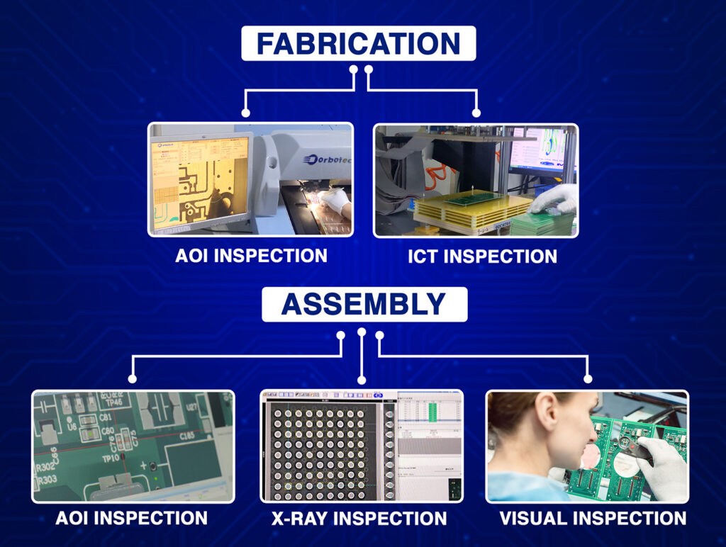
Even tiny violations can cause failures during fabrication or PCB board assembly manufacturing. In high-speed designs, they can lead to signal reflection or EMI (electromagnetic interference).
If you’re unsure whether a violation matters, ask your PCB manufacturing company. We’re happy to help you figure out if it needs to be fixed.
5. Use Net Classes for Better Rule Control
Net classes let you group similar signal types and assign specific rules to each.
For example, you might have:
- Power nets: Require wider traces and clearances
- Signal nets: Standard widths
- High-speed nets: Controlled impedance
Setting up net classes makes your rule-checking more accurate. You won’t accidentally apply a signal rule to a power trace.
This also helps when you’re working with HDI or multi-layer designs, something Blind Buried Circuits specializes in.
6. Double-Check Component Footprints
Many DRC errors come from incorrect or mismatched component footprints. These issues may not show up until PCB board assembly manufacturing when parts don’t fit.
- Verify pad sizes and spacing.
- Check that the orientation matches your BOM
- Make sure components have enough room around them for soldering.
At Blind Buried Circuits, we always recommend doing a footprint review before submitting your files. If you’re not sure, just ask, we’ll help.
7. Review Thermal Relief Rules
If your board has large copper pours (for ground or power), make sure thermal relief is enabled on pads.
Without this, pads may not heat evenly during soldering, leading to cold joints or floating components.
Use your drc design rule check settings to define the right thermal relief size and shape based on your manufacturer’s guidelines.
8. Watch for Solder Mask and Silkscreen Issues
Solder mask clearance is another common source of problems. Make sure:
- There’s enough clearance around the pads
- Vias are correctly covered or exposed.
- Silkscreen isn’t placed over pads or holes.
Your PCB board manufacturer may reject the files or fix them automatically, but it’s better to get it right yourself.
9. Simulate Before Final DRC
If your design involves high-speed or RF signals, it’s smart to run simulations before your last drc check.
Check for:
- Crosstalk
- Impedance mismatch
- Signal reflections
- Timing issues
These problems may not trigger standard DRC errors, but they can ruin board performance. At Blind Buried Circuits, we often work with high-speed digital and RF boards, and simulation is always a smart step.
10. Get a Second Set of Eyes
Before submitting your design, have someone else review it. A fresh perspective often catches what you missed, even after multiple DRC checks.
If you’re a solo designer, you can also ask your PCB manufacturing company for a quick design review. At Blind Buried Circuits, we offer DFM (Design for Manufacturability) and DFA (Design for Assembly) reviews as part of our turnkey service.
How DRC Helps You Save Time and Money
Skipping a drc design rule check might save you an hour, but cost you days or even weeks in rework.
By following the proper drc rules, you’ll avoid:
- Redesigns
- Delayed shipments
- Failed assemblies
- Higher manufacturing costs
You’ll also build stronger relationships with your pcb board manufacturer, because your designs are easier to build, and that means faster delivery.
Why Choose Blind Buried Circuits for Your PCB Project?
At Blind Buried Circuits, we don’t just manufacture PCBs. We support you at every step, from design through DRC checks, all the way to final pcb board assembly manufacturing.
Our strengths include:
- Custom PCB production with quick turnarounds
- Rigid, Flex, and Rigid-Flex boards with up to 50 layers
- Certified processes: ISO 9001, ISO 13485, IPC A-600/610
- Advanced DFM and DFA support for every project
We help you get it right the first time, so you don’t have to go back and fix costly mistakes.
Ready to Submit Your Design?
Let’s take the stress out of your next project.
Submit your design today and get a quote from our expert team. We’ll review your files, check for any issues, and guide you through the following steps.
Contact Blind Buried Circuits Today
Let’s build something that works, from the first try.


