If you want your electronic device to work well and stay reliable, you can’t ignore decoupling capacitors. These small parts help clean up the power in your circuit, keeping things smooth and steady. Placing them the right way makes a big difference. If you work with a PCB assembly company or build circuits yourself, you need to understand this key detail.
What Is a Decoupling Capacitor?
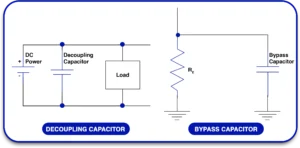
A decoupling capacitor, also known as a bypass capacitor, is a fundamental electronic component used to stabilize voltage and reduce noise within a circuit. It functions by providing a low-impedance path for high-frequency noise, essentially acting as a short circuit for these signals while maintaining the desired DC voltage. By doing so, it prevents noise from propagating through the power supply lines and interfering with other parts of the system.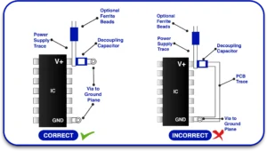
How Does It Work?
- When a sudden current spike occurs (such as when a digital IC switches states), the power supply may momentarily dip, creating voltage noise. A decoupling capacitor, placed close to the IC, supplies this transient current, thereby keeping the voltage stable.
- High-frequency noise generated by other components or external interference also gets absorbed by the capacitor, preventing it from reaching sensitive parts of the circuit.
- Essentially, the capacitor acts as a local energy reservoir, rapidly delivering charge when needed and maintaining a cleaner power supply line.
Decoupling Capacitor vs. Bypass Capacitor
Many beginners wonder about the difference between decoupling and bypass capacitors. In most practical scenarios, they are the same component, performing dual functions:
- Bypass Capacitor: Primarily used to filter out AC noise from the DC power supply, maintaining a steady DC voltage level.
- Decoupling Capacitor: Used to isolate different parts of a circuit from one another, particularly in mixed-signal designs where analog and digital circuits coexist.
The terminology often overlaps because both functions can be achieved using the same capacitor, but the context of use often dictates the term.
Why Placement Matters?
The effectiveness of a decoupling capacitor is highly dependent on its physical placement within the circuit. If the capacitor is positioned too far from the IC it is meant to protect, the added inductance and resistance of the connecting traces can significantly reduce its efficiency. This can lead to noise still reaching the IC, causing instability or glitches.
Key Points:
- Proximity: Always place the decoupling capacitor as close as possible to the IC’s power and ground pins.
- Trace Length: Minimize the trace length between the capacitor and the IC to reduce parasitic inductance.
- Direct Connection: Use thick, short traces or planes for connecting to the power and ground.
The Practical Approach
Experienced PCB manufacturers follow strict guidelines when placing decoupling capacitors, as improper placement can lead to problems such as voltage ripple, noise interference, and even functional failures. Following best practices ensures robust and reliable circuit performance, especially in high-speed or sensitive applications.
How to Place Decoupling Capacitors Correctly
Decoupling capacitors are crucial components in electronic circuits, primarily used to filter noise and stabilize voltage levels. Improper placement can lead to issues such as signal interference, voltage instability, and random resets. Here’s a comprehensive guide to placing decoupling capacitors effectively:
Key Steps to Follow:
1. Place Close to the IC:
-
- Keep the capacitor as physically close as possible to the power and ground pins of the IC.
- Shorter traces reduce parasitic inductance and resistance, improving capacitor performance.
- If space permits, use surface-mount capacitors directly adjacent to the IC pins for optimal results.
2. Use Good Grounding:
-
- A solid, low-impedance ground plane is essential. Connect capacitors directly to this plane.
- Avoid using vias between the capacitor and ground if possible, as they introduce additional inductance.
- When vias are necessary, use multiple vias to minimize resistance and inductance.
3. Select the Right Cap Value:
-
- Use a combination of capacitor sizes to cover different frequency ranges. Typically, a 0.1 µF capacitor is paired with a 1 µF capacitor.
- Small capacitors (e.g., 0.01 µF to 0.1 µF) are effective for high-frequency noise suppression, while larger capacitors (e.g., 1 µF to 10 µF) handle lower frequency fluctuations.
- Ceramic capacitors (X7R or C0G types) are preferred due to their stability and low ESR (Equivalent Series Resistance).
4. One Per Power Pin:
-
- If your IC has multiple power pins, allocate a separate decoupling capacitor to each pin.
- This ensures localized noise suppression, especially important in high-speed circuits.
5. Minimize Loop Area:
-
- The current loop formed by the power pin, capacitor, and ground must be as small as possible to minimize electromagnetic interference (EMI).
- A smaller loop area reduces the potential for radiated noise and improves high-frequency decoupling.
6. Route Power and Ground Efficiently:
-
- Use wide, short traces for power and ground connections to reduce resistance and inductance.
- When routing, maintain symmetry to prevent uneven current distribution.
- Prioritize direct, unbroken paths from the capacitor to the IC to enhance stability.
Using Decoupling Capacitors in Prototyping
- Even during prototyping, proper capacitor placement is essential. Test your setup as realistically as possible to mirror final design behavior.
- On a breadboard, keep power and ground paths as short and wide as possible. Arrange capacitors close to the IC to minimize trace length.
- On a prototype PCB, solder capacitors close to the IC pins. Use a ground plane for effective noise reduction.
Learn About: Why Are Decoupling Capacitors Essential in Circuit Design
Common Mistakes to Avoid:
- Skipping Capacitors: Never assume decoupling capacitors are optional; omitting them can result in power integrity issues.
- Inadequate Capacitance: Using only large capacitors can neglect high-frequency noise, while using only small capacitors can result in low-frequency instability.
- Improper Placement: Placing capacitors far from the IC significantly reduces their effectiveness, causing potential signal degradation.
- Thin or Long Traces: Thin or overly long traces introduce resistance and inductance, negating the benefits of decoupling.
- Single Capacitor for Multiple Pins: Sharing a capacitor among multiple power pins can cause crosstalk and insufficient decoupling.
Real-Life Tips from Manufacturers:
- PCB manufacturers often emphasize that capacitor placement is crucial for power stability and noise reduction.
- Experienced engineers know that poorly placed capacitors can cause sporadic resets or noisy signals, leading to longer troubleshooting sessions.
- If your PCB exhibits random resets or noisy operation, one of the first checks should be the decoupling capacitor layout.
Why This Matters for Your Product
You want your board to work right every time. Whether it’s a toy, sensor, or factory controller, destructive power means trouble. By following these capacitor rules, you make sure your board:
- Starts up correctly.
- Handles sudden power needs.
- Works in noisy environments.
These small changes can save you a lot of time during PCB board assembly, manufacturing, and testing.
Final Thoughts
Don’t overlook something as small as a decoupling capacitor. Its placement is one of the easiest ways to boost the quality and reliability of your board. Even if you’re just starting, it’s worth practicing good layout. Whether you’re working with a PCB manufacturer, using a PCB prototype board, or just placing a capacitor on a circuit diagram, always keep placement in mind.


