When it comes to military electronics, there’s no room for error. A single faulty board can lead to system failure or, worse, mission failure. That’s why every printed circuit board (PCB) used in defense gear must be built to the highest standards.
This blog will discuss how to design reliable PCBs for military applications and what makes them different from commercial or consumer-grade boards. Whether you’re just starting out or looking to improve your current process, this will help you focus on what truly matters: durability, performance, and safety.
Why Military PCBs Must Be Different?
Unlike regular electronics, military devices work in harsh environments, heat, cold, dust, shock, and even vibration. That’s why their PCBs must meet strict rules for strength, accuracy, and reliability.
Military PCBs are used in:
- Radar systems
- Missile guidance
- Ground communication units
- Aerospace controls
- Drones and satellites
- Night-vision systems
Each one demands top performance and zero failure. And that starts with custom PCB production made for those specific needs.
Step 1: Understand the Standards
Military boards must meet strict guidelines. In the U.S., MIL-PRF-31032 and IPC Class 3 are the most critical standards.
These standards ensure that your PCB:
- Has strong solder joints
- Works in extreme conditions
- Lasts longer without repair
- Has perfect trace spacing and hole plating
When working with a PCB manufacturing assembly partner, always ask if they follow these military-grade standards. Not all board makers do.
Step 2: Use the Right Materials
Military PCBs face heat, shock, and rough handling. So, material choice is critical.
Here are common materials used in PCB board assembly manufacturing for the military:
- High-Tg FR4: This is a strong, heat-resistant material used for many defense applications.
- Polyimide: Great for high-temperature environments like aircraft engines.
- PTFE (Teflon): Ideal for high-frequency radar systems.
Tip: Avoid low-grade FR4 materials that can delaminate or crack under pressure.
Step 3: Focus on Board Layout and Trace Design
A reliable layout is the backbone of a military PCB. Sloppy design leads to poor performance and heat buildup.
Here are some tips for layout:
- Short, direct traces: Reduce noise and signal delay.
- Use ground planes: Help with shielding and lower EMI (electromagnetic interference).
- Keep signal paths separate, Especially power and data lines.
- Add thermal reliefs To manage heat better.
All these design choices matter, especially when working with PCB assembly USA manufacturers that need precise blueprints for production.
Learn About: Best EMI and RF Sheilding Methods for Flex PCBs
Step 4: Choose High-Reliability Components
Even the best board design won’t matter if your components fail.
For military boards, always use:
- Tested components with traceable data
- Parts rated for wide temperature ranges (-55°C to +125°C)
- Moisture-resistant and vibration-proof packages
Avoid consumer-grade parts. They’re cheaper but not built to survive in the field.
Step 5: Use Redundancy and Fail-Safe Features
Military PCBs are often mission-critical. That means they should keep working even if something goes wrong.
You can do this by:
- Adding redundant circuits: Backup systems in case of failure
- Using fuse protection: To stop damage from power surges
- Designing watchdog circuits: To reset the system if it freezes.
This type of custom PCB production takes more planning, but it’s worth it in military situations.
Step 6: Plan for Rugged Assembly
Once the design is ready, the board goes through PCB board assembly manufacturing. This is where components are placed, soldered, and inspected.
In military work, assembly is just as important as design. Here’s what matters:
- Clean rooms: Keep boards free of dust or particles
- Precision soldering: Avoid cold joints or poor connections
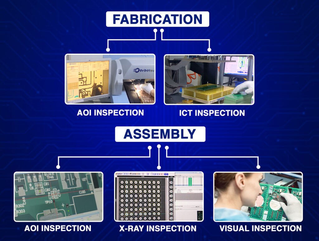
- Inspection systems: Use X-ray and AOI (automated optical inspection)
- Burn-in testing: Run the board under stress to catch early failures
Choose a PCB assembly USA company that specializes in this kind of rugged, high-stakes work. Don’t cut corners here.
Step 7: Environmental Protection
Once the PCB is complete, you still need to protect it from harsh surroundings.
Use:
- Conformal coating: A protective layer against moisture and dust
- Underfill for BGA chips: To protect against shock and vibration
- Shielding: To reduce interference from nearby systems
This final layer of defense keeps the board working even in extreme weather, high altitudes, or during combat operations.
Step 8: Thermal Management
Military devices often run hot. Think tanks, drones, or satellite systems. If you don’t plan for heat, your board could overheat and fail.
Use:
- Thermal vias: Move heat from hot areas to cool zones
- Heatsinks or heat spreaders
- Metal core boards: For ultra-high heat zones
Thermal planning is a key part of PCB manufacturing assembly, so be sure your partner understands military heat needs.
Step 9: EMI and Signal Integrity
Military devices often work around strong radio signals, radar, or jamming equipment. That means your PCB needs good shielding and signal strength.
To handle EMI:
- Use shielding cans over key components
- Route high-speed signals carefully
- Add ground and power planes.
- Use differential pair routing.
Good PCB assembly USA partners will check for signal issues early so you don’t get surprises during testing.
Step 10: Testing and Validation
Finally, every military PCB must be tested before it’s installed.
Common tests include:
- Thermal cycling: To check how it behaves in changing temperatures
- Vibration testing: Simulate real-world handling
- Burn-in testing: Run the board for 24–72 hours at high load
- Electrical testing: Make sure there are no shorts or opens
Testing makes sure the board performs under the same conditions it will face in the field. If you skip testing, you risk mission failure.
Final Thoughts
Military applications demand the best. From high heat to vibration, these boards must survive it all and still work every time. That’s why smart design, quality PCB manufacturing assembly, and careful component choices are so important.
Whether you’re upgrading radar systems, building communication tools, or designing smart drones, remember this: reliability starts at the design table. Choose a PCB board assembly manufacturing partner that understands the stakes. Use high-grade materials. Test everything. Plan for the worst. Your mission, and the safety of others, depends on it.


