Industries such as aerospace and medical devices that require high-performance circuit designs often use Rigid-flex PCBs. These PCBs are particularly useful for military purposes as well. Unlike standard rigid or flexible PCBs, rigid-flex circuits integrate the advantages of both, so they are more reliable in compact and demanding environments. Rigid-flex PCB manufacturers must comply with certain design processes IPC-2223 outlines to achieve expected results. This standard also helps reduce fabrication defects and enhance mechanical stability by providing guidelines for the flexible PCB fabrication process. Rigid-flex engineers have to deal with IPC-2223 because it exposes them to potential non-compliance risks that can lead to several manufacturing defects. In this article, I have focused on a few IPC-2223 requirements, along with common violations and practices that enable designers and manufacturers to produce high-quality rigid-flex PCBs.
What is IPC-2223?
IPC-2223 is a flexible printed circuit board industry standard that outlines the parameters and the tasks within them. It is a guideline subjected to the IPC-2220 series that defines the various types of printed circuit boards IPC-2223 offers design rules for. These include:
- Flex and Rigid Section Materials
- Transition Techniques from Rigid to Flex
- Via Routing and Placement
- Flex and Rigid Component Mounting
- Bend Radius Recommendations
- Layer Stack-Up Configuration
If rigid-flex PCB manufacturers adhere to the IPC-2223 standard, they will manufacture high-quality, reliable circuits that can bend, vibrate, and bear thermal stresses without harm.
Requirements of IPC 2223
Broadly stated, the requirements of IPC 2223 standards for the design of Rigid-Flex PCBs in outline form are:
1. Layer Stack-Up and Material Selection:
- Flex-layer materials such as polyimide will be used for rigid sections, while FR-4 will be used for the Polyimide material.
- To ensure factors such as warping and delamination do not occur within PCB Compliant, different materials must be used to ensure thermal expansion properties are compatible.
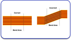
2. Bend Radius Guidelines:
- If the material has a rigid section, then conductor stress and cracking can be avoided by exceeding the material’s thickness by ten times the optimum limit of bending.
- For dynamic conditions, it is recommended that the bend radius be at least twenty times the material’s thickness to avoid material fatigue.
Mechanical strain should be avoided at solder joints and vias by steering clear from sharp bends.
3. Via and Plating Considerations
- If not necessary, through-hole vias must not be placed in flexible regions.
- In case of a necessity, additional plating and teardrop pads should be used to prevent cracking from occurring.
- In a rigid-flex design, buried and blind vias can enhance electrical performance and improve durability.
4. Component Mounting Guideline
- Rigid sections are best suited for attaching components because components placed on flex areas are prone to stress and failure.
- Reinforcement techniques like adhesive backing or stiffeners must be used if mounting in flex regions is essential.
- To mitigate soldering defects, thermal relief pads must be used on surface mount components.
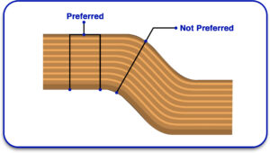
5. Flex-to-Rigid Transition Design
- Gradual stress fractures can occur if transitions between rigid and flex layers are not smooth.
- Changes in thickness should not be sudden. Otherwise, the construction may be susceptible to delamination and mechanical failure.
- To ensure durability, rigid cover lay support and adhesive bonding must be applied.
Common IPC-2223 Violations in Rigid-Flex PCB Desig
Failing to observe IPC-2223 standards can result in fabrication errors and reliability problems. Some deficiencies include the following:
1. Minimum Bend Radius Violation Is Too Large
- Overestimates the minimum required bend radius, resulting in fractured traces and delaminated surfaces.
- Rigid-flex PCB fabricators shall ensure compliance with proper bend radius calculations to ensure longevity.
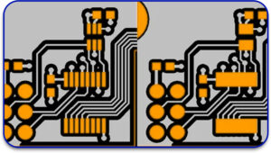
2 Poor Placement Of Vias Within Flex Areas
- Inadequate spacing of printed circuit boards (PCB) through holes within flexible regions can cause mechanical breakage and loss in signal quality.
- IPC-2223 recommends that flex sections should not contain vias unless they are suitably plated and padded.
3 Delamination Of Layers
- Wrong material selection and insufficient bonding together of layers can lead to delaminating under thermal cycling conditions.
- IPC-2223 stipulates low CTE materials so that there is no bending of the board due to uneven stress distribution.

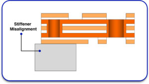
4 Stiffener Misalignment
- Stiffeners maintain structural support, but if placed in incorrect positions, they can lead to stress concentration and decreased compliance.
- IPC-2223 outlines the best practices for placement to achieve support without adverse stiffening.
5 Coverlay And Solder Mask Improper Placemen
- Coverlay materials must ensure compliance in moisture protection of flexible regions and avoid solder over bridging.
- IPC-2223 delegates the clearing of mask solder to aid in the prevention of shorting and contamination.
Best Strategies for Rigid-Flex PCB Design that is IPC-2223 Compliant:
In compliance with IPC-2223, rigid-flex PCB manufacturers should observe the following best practices to avoid overly common design mistakes and achieve compliance.
1. Optimize Layer Configuration
- FR-4 should be used in the rigid portions and high-performance polyimide in the flex layers.
- Use proper adhesive bonding to ensure no layer delamination occurs.
2. Sustain Appropriate Bend Radius
- Static flex circuits need to have a bend radius of at least 10 times the material thickness.
- In dynamic flex applications, a 20-times-thickness radius is needed to avoid material fatigue.
3. Do Not Use Flex Area Through Hole Vias
- Flexible areas should utilize blind or buried via instead.
- If through-hole vias are necessary, then reinforcement using teardrop pads and additional plating should be applied.
4. Reinforce flex to rigid transitions
- Transitions in thickness should not be sudden but gradual.
- Increase mechanical rigidity by placing stiffeners in highly stressed regions.
5. Apply Solder Masking and CoverLay Correctly
- Make sure there are no short circuits and contamination by utilizing complete overlay protection.
- Reduce defects by adhering to IPC-2223 solder mask clearances.
The Importance of Conformity to IPC-2223 Rigid-flex PCB designs need to conform to IPC-2223 standards in order to be:
- Defect-free for the complex and high-performance needs of aerospace or medical devices.
- Minimize the risk of cracking and layer separation through controlled mechanical stability.
- Reduce cost on production while maximizing efficiency to manufacture.
- The signal integrity issues have been eliminated completely. This allows an efficient use of power.
Rigid-flex PCB manufacturers that follow the IPC-2223 standard can fabricate long-lasting and reliable circuit boards for the most demanding applications.
Learn About: The Critical Impact of IPC Standards on PCB Manufacturing
Final Thoughts
The IPC-2223 standard can be used to build rigid-flex PCBs with high reliability and good performance. Following these design rules and utilizing best practices can assist flexible PCB manufacturers in mitigating defects and improving their yield, as well as enhancing the boards’ overall durability and signal integrity. It is essential to seek a reliable rigid-flex PCB fabricator to ensure the design rules are followed properly for structured quality. Whether the design is for aerospace, medical, or other industrial applications, careful adherence to IPC-2223 effectively improves the circuit board’s overall performance, strength, and profitability. Speak with an experienced PCB manufacturer like Blind Buried Circuits to access superior rigid-flex PCB services. This will allow you to confidently bring your designs to market with the utmost reliability and performance.


