Introduction:
PCBs are an essential part of modern electronics, which helps connect complex electronic parts. But does all PCBs are same? The answer is no! All the PCBs are made differently based on the application and environment where the application is required. The key role player is the PCB material, which greatly impacts the performance and cost. It is a crucial process, and we understand that a recommendation directly from your manufacturer, like Blind Buried Circuits, will help you choose the right material. At the end of this blog, you will know the following about PCB materials and their application:
- Benefits and limitations of PCB materials.
- How to choose the PCB material based on the application.
- Which material is cheaper? FR-4 or CEM-3?
- Which material is easy to find and always available with contract manufacturers.
- How can Blind Buried circuits help you in finding the right material?
Pro tip: It is always better to talk with your contract manufacturer before designing the board stack-up. With our years of experience, we can help you with the information of materials and estimated costs before your Gerber design. So what are you waiting for? Do you want to search more on materials or send us a quick email to save time and effort?
Exploring Different PCB Materials:
A diverse range of PCB materials for high-end designs is available, each with distinct properties and features. Based on the application, certain materials are more suitable, while other common materials provide a balance of performance and cost-effectiveness. The following are the most commonly used PCB materials in circuit board designs:
FR-4 (Fiber Glass):
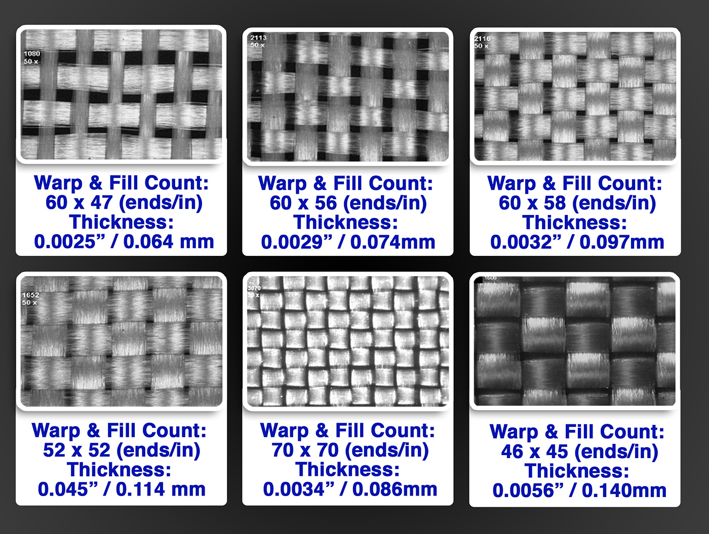
FR-4 is made of woven fiberglass cloth soaked in an epoxy resin binder and then hardened. The epoxy resin provides FR-4 with strength and durability, while the fiberglass cloth gives it electrical properties. It also varies depending on the manufacturer and application. However, all FR-4 materials must meet certain standards to be classified as FR-4.
These standards include:
- UL94V-0: To maintain flame retardance and self-extinguishing standards.
- IPC-A-600: To maintain mechanical properties and standards.
- IPC-6012: To maintain electrical properties and standards.
It is also a cost-effective material that can be used for many applications. However, knowing its benefits and limitations is important before choosing it for a specific purpose. Below are the benefits and limitations of using FR-4 material:
Benefits:
- It is a tough, long-lasting material that can endure a low coefficient of thermal expansion.
- It is an affordable and widely available material, which makes it a practical option for various purposes.
- It can be used in applications where moisture is a concern, as it absorbs near-zero water.
Limitations:
- It has a certain insulation limit, so when used in designs with high power, voltage, or heat, it conducts electricity and causes circuit failures.
- It has limitations regarding high-frequency designs as these designs contain a high risk of signal loss, and FR-4 has a high dielectric constant (Dk) and dissipation factor (Df) compared to other high-speed materials whose operating dielectric constant tolerances are less than 2%. However, FR-4 has an operating dielectric constant tolerance of up to 10%, which is not recommended for tight tolerance impedance-controlled boards.
Polyimide: Polyimide or “PI” material is synthetically produced and mainly known for its mechanical properties, thermal stability, and chemical resistance. It is expensive compared to FR-4, and only specific contract manufacturers, like Blind Buried Circuits, stock this material in-house. Below are the benefits and limitations of using Polyimide material:
Benefits:
- It possesses very minimum creep and high tensile strength.
- It has an extremely wide thermal range and can resist more than 600 °F (315 °C) of thermal stress. It is also flame combustion resistant.
- It is thin in thickness, which makes it light in weight and bends easily.
Limitations:
- All the contract manufacturers do not stock it and may supply it with a lead time.
- It is high in cost as compared to FR-4 material.
CEM-3: CEM-3 is a copper-clad laminate made with epoxy resin, glass fabric, and non-woven glass fabric as base materials. It is similar to FR-4 material but is a considerably more affordable option. It is usually considered for designs that have low TG requirements. Below are the significant benefits and limitations which tie with CEM-3 material.
Benefits:
- It is a tough, long-lasting material, like FR-4, that can endure a low coefficient of thermal expansion.
- It is more cost-effective and can be used in low-budget, simple circuit designs.
Limitations:
- It has lower thermal stability than FR-4 material, so it cannot be used in designs requiring high glass transition temperature (Tg).
- Like FR-4 material, it cannot accommodate high-frequency circuit design and may cause signal distortion.
PTFE (Teflon): PTFE material is composed of tetrafluoroethylene fluoropolymer. It has a low dielectric constant (Dk) and is considered the best material for high-frequency and microwave applications. It is very rarely available in stock and consists of long lead time. Below are the significant benefits and limitations of PTFE material:
Benefits:
- It has a low dielectric constant and loss tangent, so high-frequency designs can be manufactured using this material without signal loss and distortion.
- It has a high-temperature range from -400 to 500°F (-240 to 260°C).
Limitations:
- It is more expensive and difficult to find material. Most of the CM offer a lead time of 5-6 weeks, depending upon the availability of the material.
- It isn’t easy to manufacture, and not all the contract manufacturers offer this material.
If you require the PTFE (Teflon) material for your design, reach out before we get out of stock!
Rogers Material: A Rogers PCB is a high-frequency board made from raw materials produced by the Rogers company. Unlike conventional epoxy resin (FR4) PCB boards, it uses a ceramic base instead of glass fiber in the middle, providing better temperature stability and a stable dielectric constant. This material has a wide range of dielectric constants (DK) ranging from 2.5 to 11, which provides increased impedance stability. In comparison, FR4 material only has a DK of 4.5. Below are the significant benefits and limitations of Rogers’s material:
Benefits:
- It offers exceptional dielectric performance and signals stability for high-frequency circuit designs.
- It has a ceramic substrate that offers excellent thermal properties and high conductivity.
Limitations:
- It is expensive and difficult to find with all the contract manufacturers.
- Since Rogers offers a wide range of materials, it is recommended that you check with your CM if they stock the required material or not before starting the manufacturing.
Conclusion:
In selecting the right PCB material for your design, it is important to consider the intended use, design requirements, budget, and availability of materials. To reach that point, considering the material properties such as electrical, thermal, mechanical, chemical capabilities, and environmental factors are very important to reach the final goal. If you need further help to select the right material for your design, contact our engineering team at engineering@blindburiedcircuits.com for further guidance and suggestions on your upcoming project.

