Objective
This blog explains the most common reasons behind flexible circuit failure, the major flex PCB failure causes, and the design choices that improve long-term performance. It focuses on real-world flexible PCB reliability issues, common flexible PCB design mistakes, and practical ways to avoid early field failures.
Key Takeaways
- Most flexible circuit failures begin at the bends and transition zones.
- Poor bend radius is one of the top flex PCB failure causes.
- Copper fatigue and layer separation are common reliability issues.
- Material selection directly affects flex life.
- Wrong stiffener and coverlay choices can shorten product life.
- Early testing helps catch flexible PCB design mistakes.
- Good layout rules reduce long-term flexible circuit failure risk.
Table Of Contents
- Introduction To Flexible Circuit Reliability Challenges
- Why Flexible Circuits Fail More Often Than Rigid PCBs
- Common Mechanical Failure Points
- Material And Layer Bonding Risks
- Component, Via, And Transition Weak Points
- Environmental And Installation Risks
- Testing And Design Best Practices
- Real-World Failure Lessons
- Checklist To Avoid Common Failure Points
- Conclusion
- FAQs
Introduction To Flexible Circuit Reliability Challenges
Flexible circuits are built to bend, twist, and fit into compact products. That flexibility creates design advantages, but it also creates unique stress points that do not exist in rigid boards.
A rigid PCB mostly stays flat. A flex circuit is expected to move, fold, and survive repeated motion. That extra movement is exactly why flexible PCB reliability issues need much closer design attention.
Many field problems that look like random electrical faults actually begin as mechanical stress damage. Tiny cracks, weak bonding, poor material choices, or repeated bending in the wrong zone can slowly grow into complete flexible circuit failure.
At Blind Buried Circuits, many long-term issues come down to small design decisions made early in the layout and stack-up stage.
Why Flexible Circuits Fail More Often Than Rigid PCBs
The main difference is movement.
Every bend creates stress on copper, dielectric layers, adhesive systems, vias, and coverlay. If that stress repeats thousands of times, the weakest point eventually fails.
The most common flex PCB failure causes include:
- Copper fatigue
- Small bend radius
- Over-flexing
- Weak layer bonding
- Improper component placement
- Transition stress
- Material mismatch
- Moisture exposure
Rigid boards simply do not face the same repeated flex stress.
Trace Cracking At Bend Areas
Trace cracking is one of the most common forms of flexible circuit failure.
It usually begins in repeated bend zones where copper experiences constant stretching and compression.

Causes Of Copper Fatigue In Flex Circuits
Common causes include:
- Sharp bends
- Repeated motion cycles
- Thin trace neck-downs
- Copper grain weakness
- Wrong copper type
Design Practices To Prevent Trace Cracking
To reduce this risk:
- Use curved trace routing
- Keep traces perpendicular to bend lines
- Avoid sharp corners
- Increase trace width where possible
- Move traces away from the outer bend edge
These steps greatly reduce flex PCB failure caused by copper cracks.
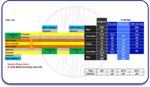
Improper Bend Radius Design
Poor bend radius design is one of the most common flexible PCB design mistakes.
Minimum Bend Radius Guidelines
A simple rule is to keep the bend radius much larger than the total circuit thickness.
Tighter bends create:
- Copper cracking
- Coverlay stress
- Layer separation
- Reduced flex life
Material Selection For Repeated Flexing
For dynamic flex:
- Use thinner copper
- Use thin polyimide
- Prefer rolled annealed copper
- Avoid thick stack-ups
The smaller the bend, the higher the flexible circuit failure risk.
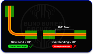
Delamination Between Layers
Layer separation is another major flexible PCB reliability issue.
Adhesive Vs Adhesiveless Construction Risks
Adhesive-based systems may weaken under heat, repeated motion, or moisture.
Adhesiveless constructions usually perform better in repeated flex conditions.
Methods To Improve Layer Bonding Strength
Best practices include:
- Better lamination control
- Material compatibility checks
- Moisture control
- Proper adhesive selection
- Lower mechanical stress zones
At Blind Buried Circuits, stack-up decisions often make the difference between long life and early delamination.
Copper Work Hardening And Metal Fatigue
Copper changes under repeated movement.
This process is one of the top flex PCB failure causes.
Rolled Annealed Vs Electro-Deposited Copper
Rolled annealed copper handles repeated flexing much better.
Electro-deposited copper is more likely to crack in dynamic bend areas.
Design Strategies To Reduce Fatigue Failure
Use:
- Larger bend radius
- Fewer flex cycles where possible
- Thinner copper
- Better trace spacing
- Controlled bend paths
Stress Concentration At Transition Zones
The rigid-to-flex interface is often a hidden weak point.
Rigid-To-Flex Interface Weak Points
This area faces:
- Sudden stiffness changes
- Higher vibration
- Installation bending stress
- Connector movement
Reinforcement Techniques For Transition Areas
Helpful methods include:
- Strain relief
- Polyimide reinforcement
- Controlled stiffener overlap
- Smooth copper transitions
Incorrect Stiffener Design
Stiffeners improve support, but wrong placement creates stress.
Stiffener Material Selection Issues
Common choices:
- FR4
- Polyimide
- Stainless steel
The wrong stiffness can increase local strain.
Proper Placement To Prevent Mechanical Stress
Never place stiffener edges too close to bend zones.
This is one of the most overlooked flexible PCB design mistakes.
Coverlay Cracking And Separation
Coverlay protects copper but can crack if too thick or too stiff.
Common Causes Of Coverlay Damage
- Tight bends
- Wrong thickness
- Misaligned openings
- Poor adhesion
- Excessive handling
Choosing The Right Coverlay Thickness
Thinner coverlay improves bend performance.
Too thick creates stiffness and a risk of cracking.
Via Failures In Flexible Circuits
Vias can fail under repeated flex stress.
Plated Through-Hole Reliability Risks
Common issues:
- Barrel cracking
- Pad lifting
- Annular ring damage
Designing Flexible-Friendly Via Structures
Best rules:
- Keep vias out of bend zones
- Use staggered structures
- Increase annular support
- Use strain relief, copper
Improper Component Placement On Flex Areas
Component placement is a major flex PCB failure cause.
Risks Of Mounting Components In Bend Zones
Placing components inside a bend area is one of the most common reasons a flex design fails earlier than expected. A bend zone is meant to move. A component is meant to stay stable. When both are forced into the same area, the mechanical stress usually gets transferred directly into the solder joints, copper pads, and surrounding layers.
Each time the circuit bends, the component adds extra weight and stiffness to that section. Instead of the flex material bending smoothly, the stress starts building around the edges of the component footprint. Over time, this repeated strain can lead to:
- Solder joint cracking
- Copper pad lifting
- Trace fractures near the pad entry
- Coverlay tearing around component openings
- Intermittent electrical opens during movement
- Early field failures after repeated flex cycles
The risk becomes even higher with larger or heavier components because the bending force is no longer distributed evenly across the flex area.
A better design approach is to keep all components in stable, non-bending zones whenever possible. If a part must stay close to a moving section, the area should be reinforced with a stiffener, and enough clearance should be left between the component edge and the nearest bend line. Small placement decisions in this area often have a major effect on long-term flex life.
Handling Mistakes That Cause Early Failure
- Twisting by hand
- Folding too sharply
- Pulling by the connector ends
- Excessive installation force
Best Practices For Assembly Teams
- Use bend guides
- Train operators
- Limit flex count
- Use fixture-based assembly
Material Selection Errors In Flexible PCB Design
Polyimide Vs Polyester Considerations
Polyimide performs better for high heat and long flex life.
Polyester works for lower-cost, low-stress uses.
Choosing The Right Thickness For Durability
Thicker is not always stronger.
Too much thickness reduces bend life.
Testing Methods To Identify Failure Points Early
Dynamic Flex Testing
Repeated bend cycle testing reveals fatigue risk early.
Thermal And Mechanical Reliability Testing
Use:
- Thermal cycling
- Peel strength tests
- Bend life validation
- Vibration testing
Design Best Practices To Prevent Flexible Circuit Failures
Best rules:
- Increase bend radius
- Use rolled annealed copper
- Avoid vias in bends
- Keep parts out of flex zones
- Reinforce transitions
- Use thin balanced stack-ups
Manufacturing Considerations For Improved Flex Circuit Reliability
Good manufacturing reduces flexible PCB reliability issues.
Focus on:
- Controlled lamination
- Copper quality
- Moisture handling
- Coverlay registration
- Clean drilling
- Better panel support
Real-World Examples Of Flexible Circuit Failures
Real failures often come from:
- Camera hinge circuits
- Medical wearable straps
- Printer head cables
- Foldable display interconnects
- Automotive dynamic harness replacements
In most cases, the root issue is a preventable flexible PCB design mistake.
Checklist To Avoid Common Flexible Circuit Failure Points
- Check the bend radius
- Use RA copper
- Keep vias out of flex
- Review stiffener edge locations
- Validate transition zones
- Test dynamic bend cycles
- Verify material thickness
- Confirm assembly handling rules
Conclusion: Designing Flexible Circuits For Long-Term Reliability
Most flexible circuit failure problems begin with small, early decisions. Bend radius, copper type, stack-up balance, stiffener placement, and transition reinforcement all affect long-term life. Understanding common flex PCB failure causes helps teams reduce flexible PCB reliability issues before the product reaches the field.
At Blind Buried Circuits, the strongest results come from preventing flexible PCB design mistakes during layout, material selection, and manufacturing planning, not after failure analysis begins.
Review bend zones, copper type, and transition areas early, most flex failures can be prevented long before the prototype is built.
FAQs About Flexible Circuit Failure Points
What Is The Most Common Flexible Circuit Failure?
Trace cracking in repeated bend zones is one of the most common failures.
Why Do Flex Circuits Fail Faster Than Rigid PCBs?
Repeated movement creates copper fatigue, layer stress, and transition damage.
What Copper Is Best For Dynamic Flex?
Rolled annealed copper is usually best for repeated flexing.
Should Vias Be Placed In Bend Zones?
No. This increases via the cracking risk.
What Is The Best Material For Long-Life Flex?
Polyimide is usually the best material for durability and heat resistance.
How Can Designers Improve Flexible PCB Reliability?
Use larger bend radius, thinner stack-ups, RA copper, and strong transition reinforcement.


