

Objective
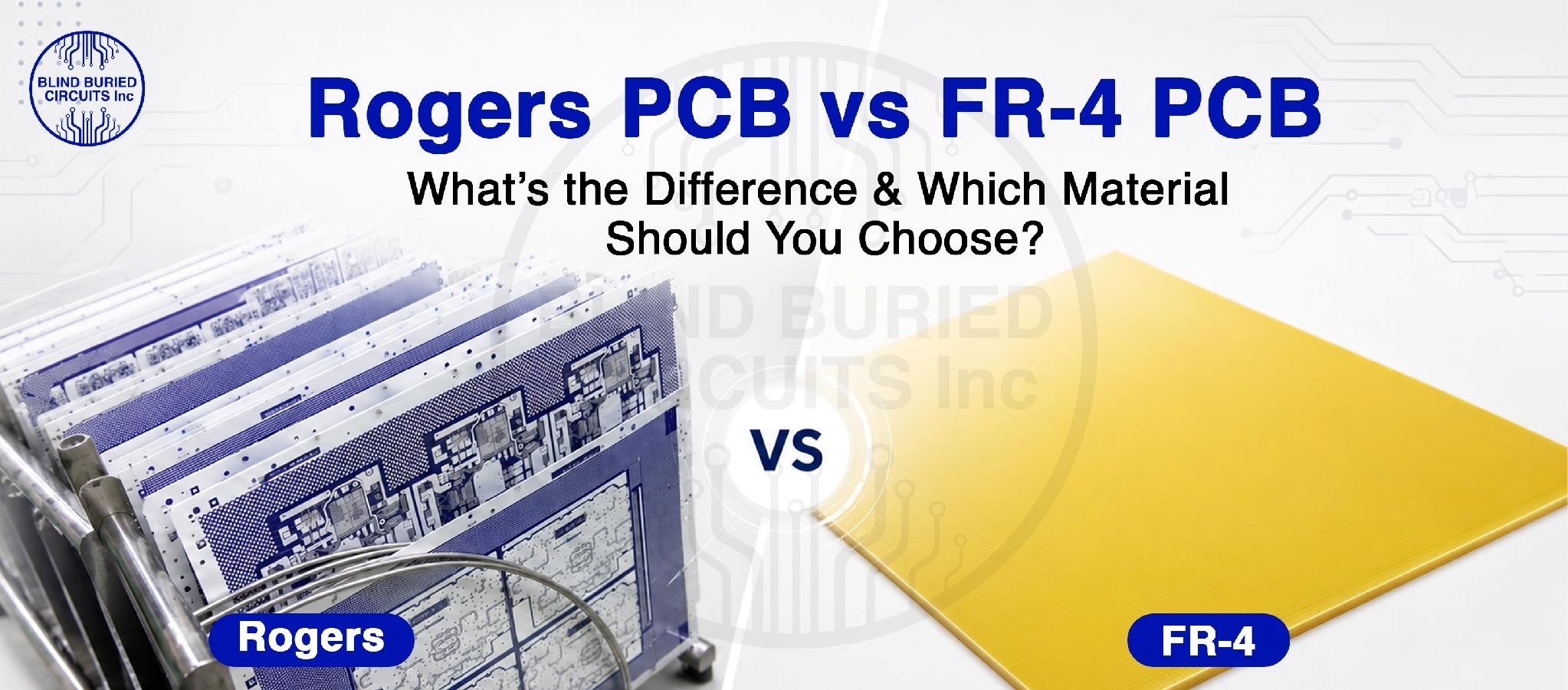
This blog explains the key differences between FR-4 and Rogers PCB materials, including their electrical, thermal, and manufacturing characteristics, to help engineers choose the right material for their PCB application.
Key Takeaways
- FR-4 is widely used for general-purpose PCB designs.
- Rogers is suitable for RF, microwave, and high-frequency PCBs.
- Dk, Df, impedance, thermal performance, and cost affect material selection.
- Different Rogers materials are designed for specific high-frequency requirements.
- The right PCB material depends on the application's electrical and manufacturing needs.
Table Of Contents
- Introduction
- What Is FR-4 PCB Material?
- What Is Rogers PCB Material?
- Rogers vs. FR4 – Understanding Key Differences
- Types of Rogers PCB Materials
- When Should You Choose FR-4 PCB Material?
- When Should You Choose Rogers PCB Material?
- How to Choose the Right PCB Material for Your Application?
- Why Choose Blind Buried Circuits for Rogers and FR-4 PCBs?
- Frequently Asked Questions
Introduction
As printed circuit board (PCB) operating frequencies increase, maintaining signal integrity becomes more difficult with conventional laminate materials. Designers must account for dielectric loss, impedance variation, propagation characteristics, thermal stability, and frequency-dependent electrical performance when selecting a substrate. This is where FR-4 or FR4 and Rogers laminates become two important material options, each suited to different circuit requirements. While FR4 material supports a wide range of general-purpose and high-speed PCB designs, Rogers materials provide tighter dielectric control and lower dielectric loss for RF and microwave applications. This post offers a detailed comparison of FR4 Vs. Rogers materials to determine which is better suited to specific PCB design requirements.
What Is FR-4 PCB Material?
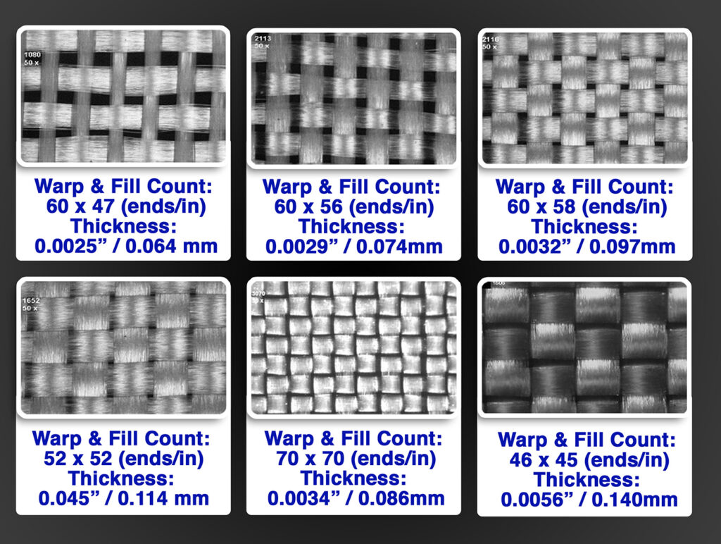
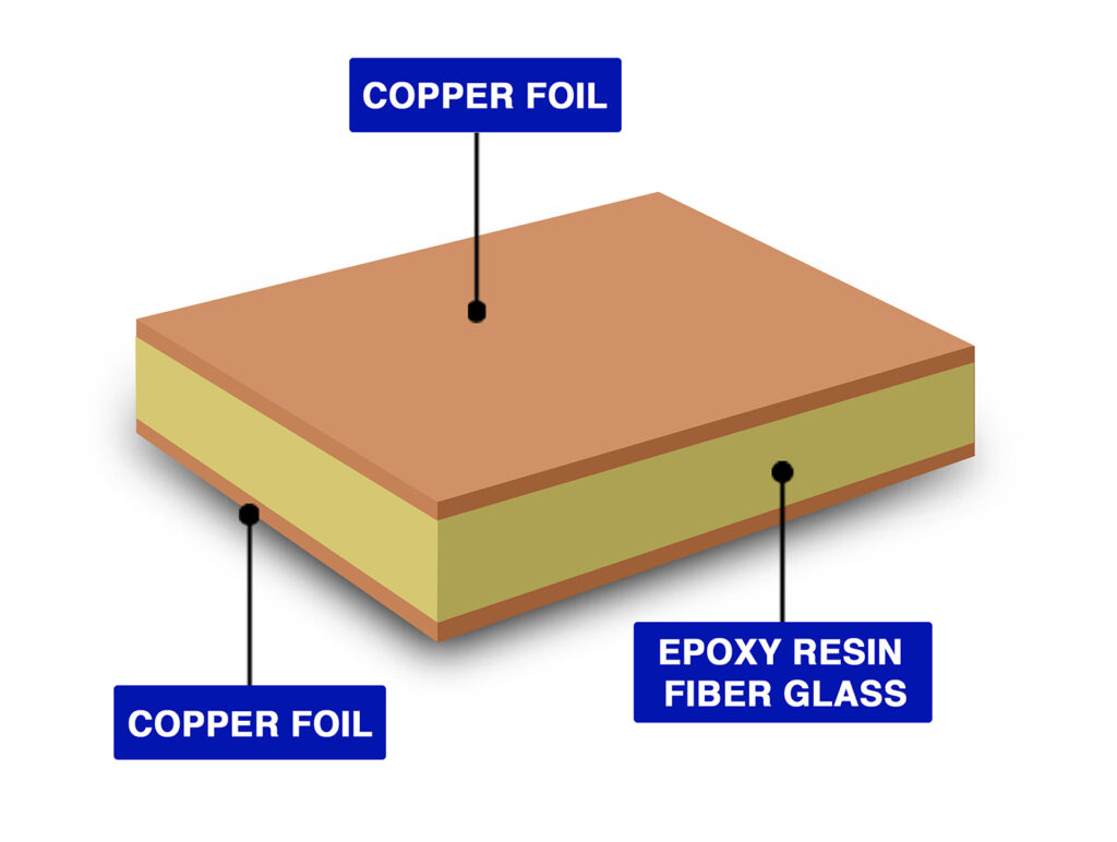
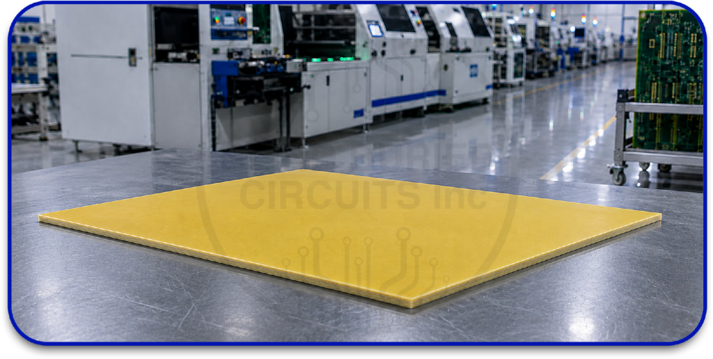
Flame Retardant (FR) 4 is a flame-retardant, glass-reinforced epoxy laminate widely used as the base material for rigid printed circuit boards. It consists of woven fiberglass impregnated with epoxy resin, with copper foil laminated onto the surface to create conductive circuit layers. This material provides mechanical strength, electrical insulation, and broad manufacturability for various electronic designs. An FR4 printed circuit board is therefore suitable for a wide range of general-purpose PCB requirements where specialized RF laminate characteristics are not necessary.
What Is Rogers PCB Material?
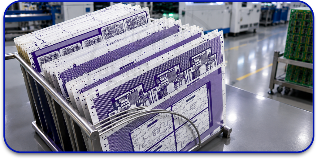
Rogers PCB material refers to a range of high-frequency laminates used for RF, microwave, and other applications that require controlled electrical performance. These materials are available in different formulations, including hydrocarbon ceramic and PTFE-based systems, with each type offering specific dielectric, thermal, and mechanical characteristics. The appropriate material grade can be selected based on the PCB’s operating frequency, dielectric requirements, thermal conditions, impedance requirements, and overall circuit design.
Rogers vs. FR4 – Understanding Key Differences
The following points differentiate FR4 and Rogers circuit board materials:
- Dielectric Constant (Dk): Dk or relative permittivity, determines electromagnetic wave propagation through the PCB dielectric and influences transmission-line dimensions, impedance, and electrical wavelength. FR-4 Dk varies with resin content, glass style, frequency, and measurement method, while Rogers laminates offer tighter dielectric control. For example, Rogers specifies a process Dk of 3.38 ± 0.05 for RO4003C and 3.48 ± 0.05 for RO4350B at 10 GHz.
- Dissipation Factor (Df)and Dielectric Loss: Df, or tan δ, indicates the dielectric loss of a PCB material and directly affects signal attenuation as frequency and transmission distance increase. FR-4 generally exhibits higher dielectric loss than dedicated RF laminates, while Rogers materials provide lower-loss formulations for high-frequency circuits. For example, RO4003C has a typical Df of 0.0027 at 10 GHz, compared with 0.0037 for RO4350B.
- High-Frequency Signal Integrity: At high frequencies, PCB traces operate as transmission lines, making dielectric loss, dispersion, conductor roughness, electrical length, and impedance discontinuities critical to signal integrity. FR-4 can support high-speed designs when its electrical characteristics and stack-up are properly controlled, while Rogers laminates provide more tightly characterized dielectric properties for demanding RF and microwave circuits.
- Impedance Control: Controlled impedance depends on dielectric constant, dielectric thickness, trace width, copper thickness, conductor geometry, and reference-plane configuration. FR-4 requires careful consideration of material and glass-weave variations during impedance design, while the tighter dielectric specifications of Rogers laminates support more predictable transmission-line calculations. Final impedance accuracy still depends on the complete stack-up and fabrication tolerances.
- Thermal Performance: Thermal performance depends on parameters such as glass-transition temperature (Tg), decomposition temperature (Td), coefficient of thermal expansion (CTE), and thermal conductivity. Rogers offers formulations designed for demanding thermal and high-frequency requirements, while FR-4 is available in multiple thermal grades. Therefore, material selection should be based on the specific laminate data sheet and the PCB’s operating and processing temperatures.
- Moisture Absorption: Moisture absorption can affect dielectric behavior and consequently influence RF performance, particularly in precision high-frequency circuits. Rogers high-frequency laminates generally offer low moisture absorption, with approximately 0.06% for RO4003C and RO4350B under the specified test condition. FR-4 moisture performance varies by formulation and should be evaluated against the application’s environmental requirements.
- Cost and Fabrication: FR-4 generally provides a lower-cost solution when the circuit does not require specialized high-frequency laminate characteristics, while Rogers materials typically involve higher material costs due to their engineered electrical properties. Fabrication requirements depend on the selected laminate and PCB construction, with some Rogers materials supporting processing methods similar to standard epoxy-glass systems. The overall cost should therefore consider material, stack-up complexity, fabrication tolerances, yield, and required electrical performance.
The following table summarizes the key differences between Rogers and FR-4 PCB materials for quick reference.
| Parameter | FR-4 PCB | Rogers PCB |
|---|---|---|
| Material system | Glass-reinforced epoxy | High-frequency laminate systems, including hydrocarbon ceramic and PTFE-based formulations |
| Dielectric constant | Formulation and frequency dependent | Material-specific and tightly characterized |
| Dissipation factor | Higher than dedicated RF laminates in many formulations | Low-loss formulations available |
| High-frequency performance | Suitable for selected high-speed designs | Optimized for RF and microwave applications |
| Impedance control | Requires careful stack-up and material characterization | More predictable due to tighter Dk control |
| Dielectric loss | Can become significant at higher frequencies | Lower loss available for RF transmission lines |
| Thermal characteristics | Vary significantly by FR-4 grade | Vary by Rogers series and formulation |
| Moisture behavior | Formulation dependent | Low-moisture formulations available |
| Manufacturing cost | Generally lower | Generally higher |
| Material availability | Broad | Depends on laminate series and supplier |
| Typical selection criterion | General-purpose PCB requirements | High-frequency electrical performance |
| Design focus | Cost, mechanical integrity, manufacturability, electrical requirements | RF performance, dielectric control, loss, impedance, and thermal requirements |
Types of Rogers PCB Materials
Rogers offers multiple laminate families because RF and microwave circuits do not have a single material requirement. Selecting the appropriate Rogers circuit board material depends on the required dielectric characteristics, operating frequency, and several other parameters.
- RO4003C: This is a hydrocarbon ceramic laminate designed for high-frequency applications. Rogers specifies a process Dk of 3.38 ± 0.05 and a dissipation factor of 0.0027 at 10 GHz. It is also designed to use processing methods similar to standard epoxy/glass PCB fabrication.
- RO4350B: This is another hydrocarbon ceramic laminate intended for RF and high-frequency applications. Its specified process Dk is 3.48 ± 0.05, with a typical dissipation factor of 0.0037 at 10 GHz. Rogers also specifies a UL 94 V-0 rating for RO4350B.
- RO3003: This is a PTFE-based ceramic-filled laminate designed for microwave and millimeter-wave applications requiring low dielectric loss and stable dielectric characteristics.
- RO3010: This is a high-Dk ceramic-filled PTFE laminate used where a higher dielectric constant is advantageous for circuit miniaturization and microwave circuit design.
- RT/duroid Series: RT/duroid materials are PTFE-based high-frequency laminates designed for demanding RF and microwave applications. Selection within this family depends on dielectric constant, loss requirements, mechanical constraints, thermal conditions, and circuit architecture.
When Should You Choose FR-4 PCB Material?
- FR-4 is generally suitable when the PCB does not require the low dielectric loss and tightly controlled electrical properties associated with specialized RF laminates. Consider FR-4 when:
- The operating frequency is within the capability of the selected FR-4 formulation.
- Cost efficiency is a significant design constraint.
- Standard PCB fabrication processes are preferred.
- The circuit contains digital, analog, power, or control circuitry without stringent RF loss requirements.
- Controlled impedance can be achieved within the available stack-up tolerances.
- The required Tg, Td, CTE, and thermal performance are satisfied by the selected FR-4 grade.
- High-frequency attenuation remains within the system’s allowable signal budget.
When Should You Choose Rogers PCB Material?
Rogers should be considered when PCB performance depends on controlled dielectric properties, low dielectric loss, and predictable high-frequency behavior. Choose Rogers when:
- RF or microwave operation is a primary circuit requirement.
- Low dielectric loss is required to control transmission attenuation.
- Tight impedance control is required.
- Dk stability is critical to phase and transmission-line performance.
- The circuit incorporates antennas, filters, couplers, RF amplifiers, or microwave transmission structures.
- High-frequency insertion loss must remain within strict limits.
- Thermal or dimensional requirements exceed the capability of the selected FR-4 grade.
- Frequency-dependent dielectric loss and dispersion significantly affect circuit performance.
How to Choose the Right PCB Material for Your Application?
The following factors should be considered when selecting between FR-4 and Rogers PCB materials.
- Define the Operating Frequency: Determine the fundamental frequency, bandwidth, harmonic content, and highest significant frequency component of the circuit. As frequency increases, dielectric loss, conductor loss, dispersion, surface roughness, and impedance discontinuities have a greater effect on signal performance.
- Establish the Required Dk: Select a laminate based on its dielectric constant at the circuit’s operating frequency. For controlled-impedance designs, use manufacturer-specific Dk data rather than relying on a generic FR-4 value, since Dk varies with material formulation, frequency, and construction.
- Evaluate Dissipation Factor: Evaluate the material’s dissipation factor against the allowable dielectric attenuation of the transmission path. A lower dissipation factor becomes increasingly important for high-frequency circuits and longer signal paths where dielectric loss can significantly affect transmission performance.
- Determine the Impedance Requirement: Define the required single-ended or differential impedance and evaluate the parameters that influence it, including dielectric thickness, trace width, copper thickness, copper roughness, Dk, trace geometry, reference-plane spacing, and fabrication tolerances.
- Evaluate Thermal Requirements: Select a material that satisfies the circuit’s thermal requirements by evaluating Tg, Td, CTE, thermal conductivity, operating temperature, thermal cycling, copper density, and heat dissipation requirements. The selected laminate must maintain its electrical and mechanical characteristics throughout the expected thermal profile.
- Consider Manufacturing Constraints: Verify that the selected laminate is compatible with the PCB manufacturer’s fabrication capabilities, including lamination, drilling, via structures, sequential lamination, surface finish, copper thickness, registration tolerances, and controlled-impedance requirements. Material selection should align with the intended board construction and manufacturing process.
- Compare Total Cost: Evaluate total PCB cost rather than laminate price alone. Consider material availability, fabrication yield, stack-up complexity, testing requirements, machining, manufacturing volume, and additional processing requirements when comparing FR-4 and Rogers PCB materials.
- Use Manufacturer-Specific Material Data: Use the exact manufacturer’s material data for engineering calculations involving both FR-4 and Rogers PCB materials. This is particularly important for high-frequency designs because Dk and dissipation factors vary with frequency and directly influence transmission-line performance.
Why Choose Blind Buried Circuits for Rogers and FR-4 PCBs?
From circuit board FR4 material selection to final fabrication, every PCB parameter must align with the circuit’s electrical and mechanical requirements. Blind Buried Circuits offers FR-4 and Rogers PCB manufacturing, PCB assembly, HDI fabrication, and controlled-impedance solutions for prototype and production requirements. Our circuit board material FR4 options and Rogers PCB capabilities support different electrical, thermal, and high-frequency requirements. Submit your PCB requirements today and get the manufacturing support your design demands.