

Objective
To explain the essential PCB manufacturing files, including Gerber files, fabrication drawings, and assembly documentation, while helping PCB designers and engineers prepare accurate, complete, and production-ready data for reliable PCB fabrication and assembly.
Key Takeaways
- Understand the essential files required for PCB fabrication and assembly.
- Learn the differences between Gerber RS-274X, Gerber X2, ODB++, and IPC-2581 formats.
- Identify the importance of accurate drill files, layer stack-ups, BOMs, and pick-and-place data.
- Follow best practices for file verification, revision control, and manufacturing documentation.
- Reduce manufacturing errors, rework, and production delays through proper file preparation.
Table Of Contents
- Introduction
- Essential Files Required for PCB Manufacturing
- Gerber X2 vs. RS-274X vs. ODB++ vs. IPC-2581: Which Format Should You Use?
- Best Practices for Preparing PCB Manufacturing Files
- Validate Your PCB Data Before Production
- Frequently Asked Questions
Introduction
As PCB designs become more complex, accurate and complete manufacturing documentation is essential for reliable production. Multilayer stack-ups, controlled-impedance structures, high-density routing, and advanced interconnections require precise manufacturing data to translate the design intent into the electrical, mechanical, and assembly requirements needed for production. Before fabrication begins, manufacturers need appropriate production outputs that define layer artwork, drilling, stack-up, board dimensions, component placement, and assembly requirements. The PCB Gerber file is a key element of this package, but Gerber data alone does not fully define every manufacturing and assembly requirement. Additional PCB fabrication files and assembly documentation may be required depending on the board design, fabrication process, and assembly requirements.
This guide explains the essential files required for PCB manufacturing, compares commonly used manufacturing data formats, and outlines practical best practices for preparing accurate, production-ready documentation.
Essential Files Required for PCB Manufacturing
A production-ready PCB package typically includes fabrication files for board construction, assembly files for component placement, and additional files for testing and project-specific requirements. Together, these files provide the information needed for PCB fabrication, assembly, and inspection.
- Fabrication Files: These files communicate the PCB layer artwork, drilling information, board dimensions, and fabrication requirements. Electrical connectivity may be verified using a separate netlist or connectivity information included in supported manufacturing data formats.
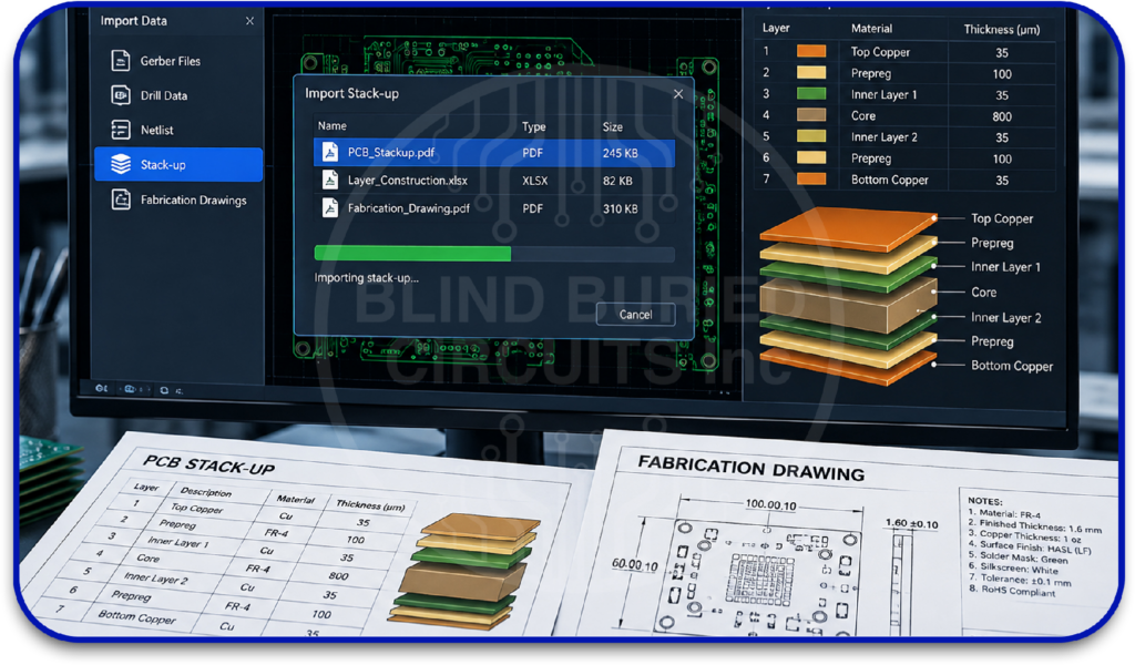
- Gerber Files: A Gerber package typically defines the artwork for each PCB layer, including copper, solder mask, silkscreen, paste, and board outline. Each PCB Gerber file should be correctly exported and checked to prevent missing layers, polarity errors, or fabrication discrepancies. Reviewing the Gerber output before release helps verify that the manufacturing data matches the intended PCB design.
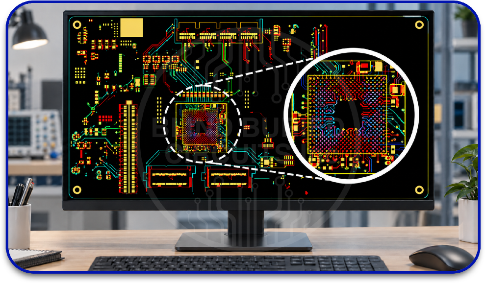
NC Drill Files: NC drill files define the location and size of drilled features, including vias, plated through-holes, mounting holes, and slots. Complex multilayer PCB boards may require multiple drill files to distinguish different hole sizes, plating requirements, or fabrication features.
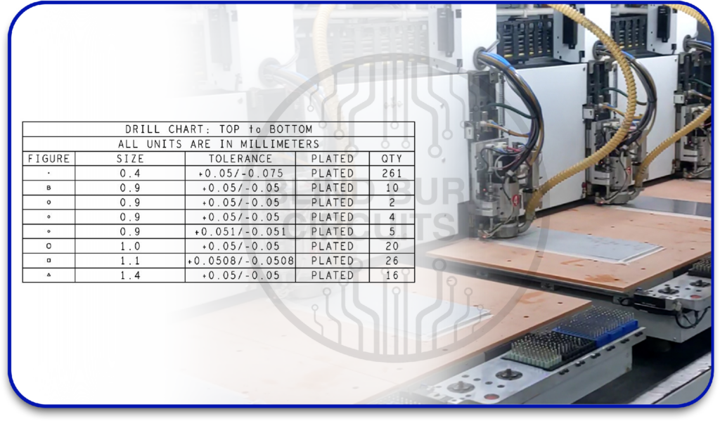
Netlist: A netlist defines electrical connectivity between components and PCB features. Manufacturers can compare it with the exported design data to identify potential connectivity discrepancies before fabrication, providing an additional verification step.
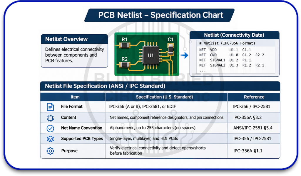
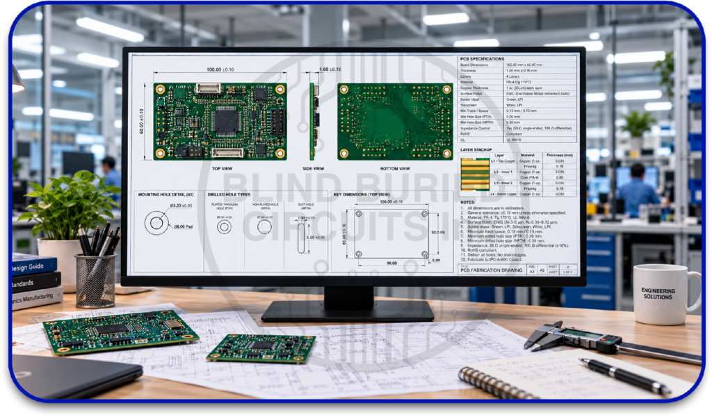
Fabrication Drawing: This drawing communicates key manufacturing specifications, including board dimensions, tolerances, materials, surface finish, thickness, impedance requirements, and special processing instructions.
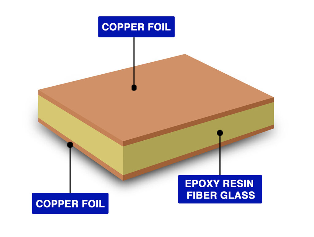
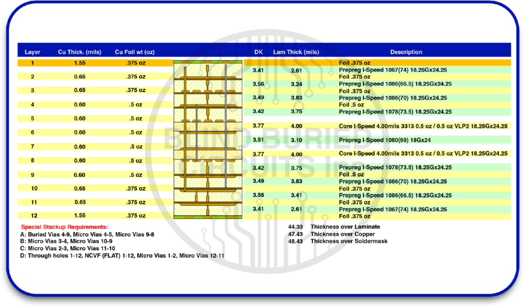
Layer Stack-Up: The stack-up specifies the arrangement, materials, and thicknesses of copper and dielectric layers. It is essential for multilayer and high-speed designs because it affects impedance, signal integrity, and mechanical characteristics. The stack-up should be verified against the fabrication documentation before production.
Assembly Files: These files provide the information required to source, place, orient, solder, and inspect components on the fabricated PCB.
- PCB Bill of Materials (BOM) File: The BOM lists the components required for assembly, including reference designators, manufacturer part numbers, descriptions, quantities, package details, and approved alternatives. Accurate BOM data supports procurement, component verification, and assembly planning.
- PCB Pick and Place File: This file provides automated assembly equipment with each component’s reference designator, X-Y coordinates, rotation, and board side. Accurate placement data supports correct component positioning and should be verified against the latest PCB layout and assembly requirements before production.
- Top and Bottom Assembly Drawings: Assembly drawings show component locations, designators, orientations, and placement details on both board sides. They provide a visual reference for assemblers, inspectors, and engineers during production and quality checks. Together, these documents provide key references for PCB assembly and inspection.
Additional Files: Additional documentation may not be required for every project, but it can provide important information for testing, inspection, and project-specific manufacturing requirements.
- Test Point File: A test point file identifies designated locations for electrical testing and verification. It can support flying-probe testing, in-circuit testing, functional testing, and other production test methods. Providing clearly defined test points can help simplify test development and support verification of complex boards.
- Manufacturing Notes or README File: Manufacturing notes or a README file can document special handling, panelization, inspection, revision, material, and impedance requirements. Including these details with the PCB manufacturing documentation gives manufacturers additional production guidance and can reduce clarification requests.
Gerber X2 vs. RS-274X vs. ODB++ vs. IPC-2581: Which Format Should You Use?
PCB manufacturing formats differ mainly in how they structure, communicate, and integrate design and production data. The following comparison highlights the key differences between RS-274X, Gerber X2, ODB++, and IPC-2581.
| Differentiating Factor | RS-274X | Gerber X2 | ODB++ | IPC-2581 |
|---|---|---|---|---|
| File Structure | RS-274X uses separate Gerber files to represent individual PCB layers and manufacturing features. | Gerber X2 retains the Gerber file structure while adding standardized attributes that provide additional information about the data. | ODB++ organizes manufacturing information in a structured data format rather than relying primarily on separate layer files. | IPC-2581 uses a structured XML-based data format to organize PCB design and manufacturing information. |
| Information Scope | It primarily communicates graphical PCB artwork, while drill, stack-up, and other manufacturing information are typically supplied separately. | It adds attributes such as layer function, polarity, part information, and pad function to Gerber data, providing additional manufacturing context. | It can contain fabrication, assembly, component, and other production information within a structured data package. | It can communicate fabrication, assembly, material, component, and test information within a standardized data package. |
| Fabrication & Assembly Integration | Fabrication and assembly information are generally provided through separate fabrication documentation, BOMs, drawings, and assembly data. | It adds manufacturing context to Gerber data but does not by itself replace all fabrication or assembly documentation. | It can integrate fabrication and assembly information within the same structured data package. | It supports fabrication, assembly, and inspection data within a unified data format. |
| Automation & Data Interpretation | It provides graphical manufacturing data but may require additional files and documentation to communicate the full manufacturing intent. | Embedded attributes provide additional context and can support automated data interpretation. | Its structured data model can support automated manufacturing workflows and reduce manual data handling. | Its standardized structure can support automated data exchange across design, manufacturing, assembly, and inspection processes. |
| Compatibility & Typical Use | RS-274X has broad support across PCB CAM systems and can be suitable when widely supported Gerber manufacturing data is required. | Gerber X2 is suitable for Gerber-based workflows that need additional manufacturing information while retaining compatibility with the Gerber format. | ODB++ is suited to manufacturing workflows that require a structured representation of fabrication and assembly data. | IPC-2581 is suited to digital manufacturing environments requiring structured, vendor-neutral data exchange. |
The appropriate format depends on the PCB manufacturer’s capabilities and the requirements of the project. Before exporting PCB Gerber files or other manufacturing data, confirm the required format with your manufacturer. This helps ensure that the supplied manufacturing data is compatible with the manufacturer’s CAM and production systems.
Best Practices for Preparing PCB Manufacturing Files
Creating production-ready documentation requires more than exporting design outputs. Each file should be reviewed for accuracy, consistency, and completeness before release. The following practices help reduce manufacturing errors, clarification cycles, and delays during PCB fabrication and assembly.
- Verify Outputs: Review every PCB design Gerber file with an independent Gerber viewer before release. Check for missing layers, incorrect apertures, board outline errors, silkscreen conflicts, polarity issues, and other inconsistencies. This verification helps confirm that the exported manufacturing data represents the intended PCB design.
- Control Revisions: Keep the same revision level across fabrication drawings, BOMs, assembly files, and manufacturing outputs. Track every released file against the approved design revision to prevent outdated data from reaching production. Consistent revision control improves traceability and can help prevent component mismatches, fabrication errors, and production delays.
- Standardize Layer Names: Use clear and consistent file names to identify layer functions, such as Top Copper, Bottom Copper, Top Mask, Bottom Mask, Drill, and Board Outline. Standardized naming helps manufacturers identify each layer quickly, reduces ambiguity, and can help prevent incorrect layer assignments during PCB fabrication.
- Provide Complete Files: Do not rely solely on a PCB Gerber file package for production. Provide the required Gerber outputs, drill files, stack-up information, fabrication drawings, BOM, pick-and-place data, and assembly drawings based on the requirements of the PCB fabricator and assembly provider. Providing the required documentation gives manufacturers the information needed for the applicable fabrication and assembly processes.
- Check Assembly Data: Verify component coordinates, rotations, reference designators, footprints, and board-side information before releasing assembly documentation. A PCB engineer or manufacturing engineer can review placement and orientation data for discrepancies that may not be apparent during layout review, helping reduce the risk of assembly errors and rework.
- Match Design Intent: Keep the design database consistent with the exported manufacturing documentation throughout the PCB design and release workflow. Verify net connectivity, drill locations, layer alignment, stack-up details, and assembly information before release. Consistent manufacturing data helps carry the intended design requirements into fabrication and assembly.
- Review the Final Package: Review the complete PCB manufacturing package as one manufacturing set before release. Confirm that all required files are present, revisions match, and documentation remains consistent across the package. This final review can help identify fabrication delays, data discrepancies, and unnecessary revision cycles before production.
Validate Your PCB Data Before Production
Review your PCB documentation before production to identify missing layers, incorrect drill data, revision inconsistencies, or incomplete assembly files that could lead to rework or production delays. Blind Buried Circuits Inc provides support for reviewing Gerber files, stack-ups, fabrication data, and assembly documentation for complex multilayer and HDI PCBs with blind and buried vias. Share your PCB manufacturing requirements with the Blind Buried Circuits Inc team to review your documentation and confirm the data required for your project.