

Objective
This blog explains fiberglass PCBs, FR-4 materials, common PCB constructions, material selection, benefits, and applications.
Key Takeaways
- Fiberglass PCBs use glass-fiber-reinforced laminates for strength and dimensional stability.
- FR-4 is widely used for rigid PCBs, with different grades offering different properties.
- Fiberglass-based materials are used in single-layer, double-layer, multilayer, HDI, and other PCB constructions.
- Material selection depends on thermal, electrical, mechanical, environmental, and manufacturing requirements.
- Fiberglass-reinforced PCBs are widely used in consumer, automotive, industrial, telecommunications, and medical electronics.
Table Of Contents
-
- Introduction
- What Is a Fiberglass PCB?
- Is Glass Fiber the Same as Fiberglass?
- Understanding FR-4: The Most Common Fiberglass PCB Material
- Types of PCBs Using Fiberglass-Based Materials
- Benefits of Fiberglass PCBs
- How to Choose the Right Fiberglass PCB Material
- Applications of Fiberglass Circuit Boards
- Need the Right Fiberglass PCB for Your Application?
- Frequently Asked Questions
Introduction
Material selection becomes increasingly critical as printed circuit board (PCB) architectures move toward higher layer counts, tighter geometries, and more complex interconnect structures. As technologies such as blind and buried vias enable greater circuit density, manufacturers require substrates that can maintain mechanical stability, electrical insulation, and thermal reliability throughout fabrication and operation.
Fiberglass-reinforced laminates, particularly FR-4, are widely used in rigid PCB fabrication because they provide a practical balance of electrical, mechanical, thermal and manufacturing properties. Widely used across consumer electronics, telecommunications, automotive, and industrial applications, fiberglass PCB materials offer an optimal balance of performance, manufacturability, and cost. This post explores the properties, benefits, applications, and FR-4 characteristics that make fiberglass-based PCBs a foundation of modern electronic design.
What Is a Fiberglass PCB?
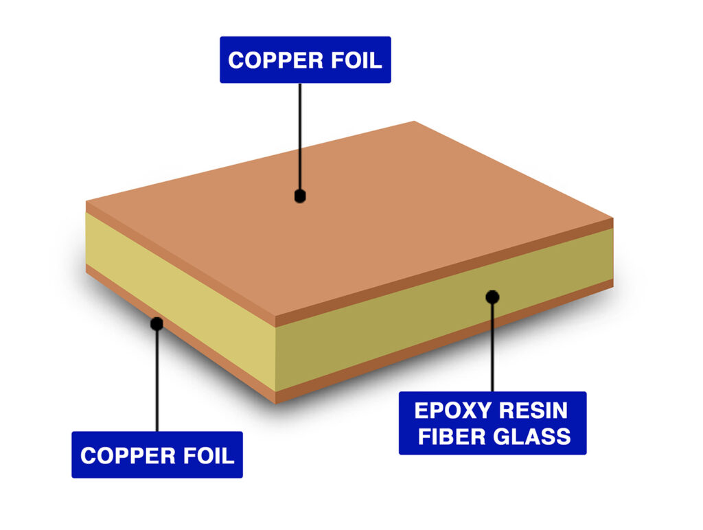
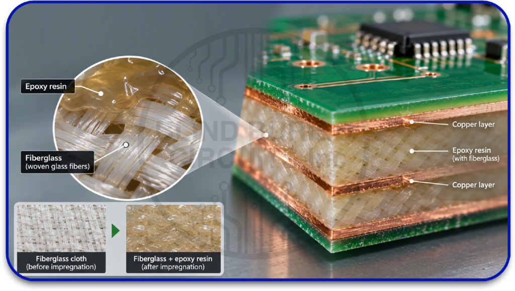
A fiberglass PCB is a printed circuit board built on a laminate reinforced with woven glass fibers and bonded with an epoxy resin system.
A typical fiberglass PCB consists of several functional layers:
- Woven fiberglass: Provides structural reinforcement and helps maintain the board’s dimensional stability.
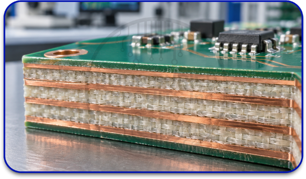
- Epoxy resin: Surrounds the glass fibers and provides electrical insulation while bonding the laminate together.
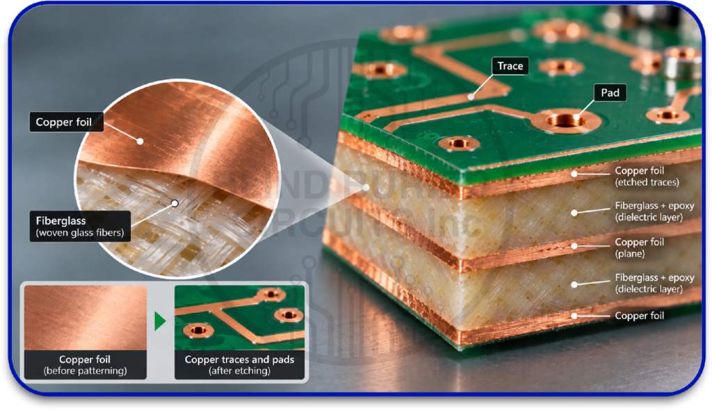
- Copper foil: Forms the conductive layers used to create traces, planes, pads, and other circuit features.
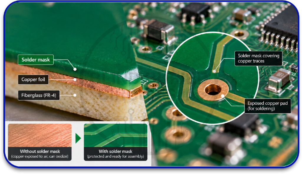
- Solder mask: Protects exposed copper from oxidation and helps prevent solder bridges during assembly.
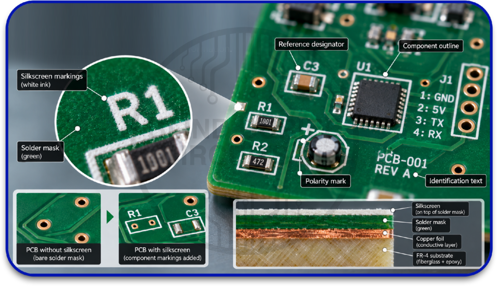
- Silkscreen: Provides component markings, reference designators, and other identification information.
In multilayer PCBs, multiple fiberglass-reinforced dielectric layers are combined with patterned copper layers. The individual layers are aligned and laminated under controlled heat and pressure to create a rigid, integrated structure. This construction is particularly important for advanced designs where accurate layer registration is required for features such as blind and buried vias.
Is Glass Fiber the Same as Fiberglass?
Glass fiber and fiberglass are closely related terms, but they are not exactly the same. Glass fiber refers to the individual fine fibers made from glass, while fiberglass generally refers to a material made using these glass fibers as reinforcement.
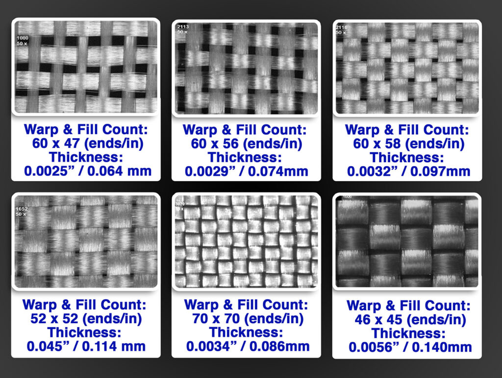
In PCB manufacturing, glass fibers are commonly woven into glass cloth and combined with an epoxy resin system to form a reinforced laminate. The glass reinforcement provides mechanical strength and dimensional stability, while the resin provides electrical insulation and binds the structure together.
This glass-fiber reinforcement is a key part of materials such as FR-4, which is widely used for rigid PCBs. The final laminate’s electrical, thermal, mechanical, and dimensional properties depend on the combination of glass reinforcement, resin formulation, and laminate construction not on the glass fibers alone.
Understanding FR-4: The Most Common Fiberglass PCB Material
FR-4 is the most widely used material for rigid PCBs and is a standard choice for multilayer circuit designs. Its designation identifies a flame-retardant glass-reinforced epoxy laminate, while different FR-4 grades offer varying electrical and thermal characteristics. Understanding these variations is important when selecting a fiberglass PCB material for a specific application.
What Does FR-4 Mean?
- FR stands for Flame Retardant, referring to the laminate’s ability to meet defined flammability requirements.
- 4 identifies the specific glass-reinforced epoxy laminate category within the material classification system.
- FR-4 is not a single standardized formulation. Different grades can have different glass transition temperatures (Tg), decomposition temperatures (Td), dielectric properties, and coefficients of thermal expansion.
- Engineers therefore select an FR-4 grade according to the board’s thermal, electrical, mechanical, and reliability requirements.
Types of PCBs Using Fiberglass-Based Materials
Fiberglass-reinforced laminates are used across different PCB configurations depending on circuit complexity, routing density, electrical requirements, thermal conditions, and mechanical constraints. The major types and constructions include:
- Single-Layer PCBs: Single-layer PCBs have one conductive copper layer on an insulating substrate. They are suitable for relatively simple circuits with limited routing requirements. Fiberglass-reinforced laminates are used when the design requires a rigid, mechanically stable substrate.
- Double-Layer PCBs: Double-layer PCBs have conductive copper layers on both sides of the insulating substrate, with plated through-holes providing electrical connections between them. They offer greater routing capacity than single-layer boards and are widely used for moderately complex electronic circuits. FR-4 is commonly used as the fiberglass-reinforced substrate for these rigid PCBs.
- Multilayer PCBs: Multilayer PCBs contain three or more conductive copper layers separated by dielectric material and laminated into a single structure. They provide higher routing density and allow the integration of power and ground planes within the board. Fiberglass-reinforced FR-4 laminates are widely used for conventional multilayer PCBs, including designs incorporating through, blind, and buried vias.
- HDI PCBs: High-Density Interconnect (HDI) PCBs use advanced interconnection technologies to achieve higher routing density within a smaller board area. They can incorporate microvias, blind vias, buried vias, and stacked or staggered via structures. Fiberglass-reinforced laminates, including suitable FR-4 grades, are used in HDI construction when their electrical, thermal, and dimensional characteristics meet the design requirements.
- Thick-Copper Fiberglass PCBs: Thick-copper PCBs use heavier copper layers than conventional circuit boards to support higher current loads and improve heat distribution. A fiberglass-reinforced laminate can serve as the dielectric substrate when its thermal and mechanical properties are appropriate for the application. These PCBs are commonly used in power electronics, automotive systems, industrial equipment, and other high-current applications.
Benefits of Fiberglass PCBs
Fiberglass-reinforced PCB materials offer a balanced combination of mechanical stability, electrical insulation, thermal performance, and manufacturing compatibility. These characteristics make them suitable for a broad range of rigid circuit-board designs.
- High Mechanical Strength and Structural Stability: Fiberglass reinforcement gives the PCB substrate high stiffness and strength, helping the board resist bending, deformation, and mechanical stress during fabrication, PCB assembly, and operation. This structural stability is particularly valuable in multilayer boards and other complex PCB constructions.
- Reliable Electrical Insulation: Fiberglass-based laminates provide dependable electrical isolation between conductive layers and circuit features. Their dielectric properties can also be engineered or selected to meet different electrical requirements, making them suitable for conventional digital, analog, power, and certain high-speed PCB applications.
- Good Thermal-Cycling Performance: Fiberglass PCB materials can withstand the thermal conditions associated with soldering, assembly, and normal electronic operation. Higher-performance laminate grades can provide increased Tg, improved resistance to thermal degradation, and lower Z-axis expansion, supporting greater reliability during repeated thermal excursions.
- Dimensional Stability for Multilayer and High-Density Designs: The glass reinforcement helps control dimensional changes in the laminate, which supports accurate layer registration and interconnection alignment. This is particularly important in multilayer and HDI boards, where small dimensional variations can affect fine features, vias, and layer-to-layer connections.
- Broad Manufacturing Compatibility: Fiberglass-reinforced laminates can be processed using established PCB manufacturing methods, including lamination, drilling, copper plating, and pattern formation. Depending on the laminate grade and construction, they can support multilayer fabrication, sequential lamination, and advanced interconnection structures such as blind and buried vias.
- Wide Range of Material Options: Fiberglass is not a single PCB material with fixed performance characteristics. Different glass styles, resin systems, fillers, and laminate formulations can be combined to achieve different Tg, CTE, dielectric, moisture-resistance, and reliability characteristics. This allows engineers to select a fiberglass-reinforced material according to the electrical, thermal, mechanical, and reliability requirements of the application.
How to Choose the Right Fiberglass PCB Material
Selecting a fiberglass PCB material requires more than choosing a standard laminate. The material should match the board’s operating environment, electrical requirements, layer structure, and manufacturing process.
- Consider the Operating Temperature: Choose the laminate according to the maximum operating temperature and expected thermal cycling of the PCB. Parameters such as glass-transition temperature (Tg), decomposition temperature (Td), and Z-axis CTE help determine whether a material can withstand the application’s thermal conditions. High-Tg or other high-performance fiberglass laminates may be appropriate for boards exposed to elevated temperatures or repeated thermal excursions.
- Match the Material to Electrical Requirements: Evaluate the laminate’s dielectric constant (Dk) and dissipation factor (Df) when signal integrity, controlled impedance, or high-speed transmission is important. Standard fiberglass laminates can support many conventional digital, analog, and power applications, while designs with more demanding electrical requirements may require a laminate with tighter and more stable dielectric characteristics.
- Evaluate Layer Count and Interconnection Structure: The PCB’s layer count and interconnection technology should influence material selection. Multilayer boards, HDI structures, and designs incorporating blind or buried vias require appropriate dimensional stability, thermal performance, and Z-axis expansion characteristics to maintain reliable layer registration and interconnections. Material data should therefore be reviewed alongside the intended lamination and via structure.
- Check Mechanical and Environmental Requirements: Consider factors such as flexural strength, dimensional stability, moisture absorption, and chemical resistance when the PCB will operate in demanding mechanical or environmental conditions. Moisture can also affect laminate properties, including thermal and electrical behavior, so the material’s specified moisture performance should be considered for applications exposed to humidity or repeated environmental changes.
- Balance Performance With Manufacturing and Cost: The selected material should provide the required performance without introducing unnecessary material or processing costs. Standard fiberglass laminates are well established and relatively economical, while higher-performance grades can provide improved thermal, electrical, or reliability characteristics where required. Confirm that the chosen laminate is compatible with the intended lamination, drilling, plating, soldering, and assembly processes before finalizing the material.
Applications of Fiberglass Circuit Boards
Fiberglass circuit boards are widely used where mechanical strength, electrical insulation, thermal stability, and reliable multilayer fabrication are required. Choosing the right fiberglass circuit board material helps ensure the PCB meets the electrical, thermal, mechanical, and environmental requirements of the application.
- Consumer Electronics: Fiberglass PCBs are used in smartphones, computers, televisions, appliances, and other electronic devices requiring compact, rigid, and reliable circuit-board construction.
- Automotive Electronics: They are used in control units, infotainment systems, sensors, lighting, and other automotive electronics where dimensional stability and resistance to thermal cycling are important.
- Industrial Equipment: Fiberglass circuit boards support industrial controllers, automation systems, power supplies, instrumentation, and monitoring equipment that require durable and electrically stable substrates.
- Telecommunications: They are used in networking equipment, communication systems, and data-processing hardware where multilayer construction, controlled impedance, and reliable signal routing are required.
- Medical Electronics: Fiberglass PCBs are used in diagnostic equipment, monitoring systems, imaging devices, and other medical electronics requiring consistent electrical performance and reliable long-term operation.
Need the Right Fiberglass PCB for Your Application?
Looking for a reliable PCB manufacturing partner? Blind Buried Circuits supports FR-4, multilayer, HDI, and custom rigid PCB designs, with engineering assistance for complex stack-ups, impedance control, and advanced interconnections. Connect with their team to discuss your PCB requirements and manufacturing needs.